magicolor 2210 User’s Guide ® 1800669-001B EDNord - Istedgade 37A - 9000 Aalborg - telefon 96333500
Trademarks The following are registered trademarks of MINOLTA-QMS, Inc.: QMS, the MINOLTAQMS logo, Crown, CrownNet, and magicolor. Minolta is a trademark of Minolta Co., Ltd. Other product names mentioned in this guide may also be trademarks or registered trademarks of their respective owners. Proprietary Statement The digitally encoded software included with your printer is Copyrighted © 2001 by MINOLTA-QMS, Inc. All Rights Reserved.
Contents 4 5HSODFLQJ &RQVXPDEOHV 1111111111111111111111111111111111111111111111111111111111111111111111111111111111 8 &RQVXPDEOH /LIH ([SHFWDQFLHV 9 5HSODFLQJ &RQVXPDEOHV 9 2UGHULQJ &RQVXPDEOHV ; 5HSODFLQJ 7RQHU &DUWULGJHV ; 7RQHU &DUWULGJH /LIH ; 7RQHU &DUWULGJH +DQGOLQJ < 7RQHU &DUWULGJH 5HSODFHPHQW 43 5HILOOHG 7RQHU &DUWULGJHV 45 5HSODFLQJ WKH 23& 'UXP .
2 Using Media .....................................................................................................33 Introduction 34 Media Handling 34 Media Types 35 Plain Paper 35 Letterhead and Memo Media 35 Thick Stock 36 Envelopes 37 Labels 37 Postcards 38 Transparencies 38 Loading Media 40 Autoduplexing 40 Upper and Optional Media Trays 41 Multipurpose Tray 43 Printing Envelopes from the Multipurpose Tray 45 Printing Area 46 Media Storage 46 3 Maintaining the Printer ...............................
Solving Problems with Printing Quality 74 Status, Error, and Service Messages 85 Status and Error Messages 85 Service Messages 94 HP-GL, HPXL, and PCL Error Codes 97 PostScript Errors 98 Additional Assistance 98 5 Installing Other Accessories ..........................................................................
7 Repacking the Printer ...................................................................................
Replacing Consumables 1 EDNord - Istedgade 37A - 9000 Aalborg - telefon 96333500
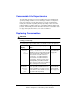
Consumable Life Expectancies The stated life expectancy of each consumable is based on printing under specific operating conditions, such as media type, number of color planes, page size, and page coverage (@ normal 5% coverage of letter/A4-size media). The actual life expectancy will vary depending on these and other printing variables, including continuous or intermittent printing, ambient temperature, and humidity.
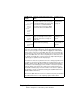
Item/Message Display This item needs replacing by user after... OPC drum kit** REPLACE OPC DRUM REPLACE WASTE TONER WASTE TONER NEAR FULL Up to 30,000 continuous monochrome “Replacing the or 7,500 continuous four-color pages, OPC Drum Kit” or 10,000 intermittent [one-page jobs] on page 13 monochrome or 5,000 intermittent [one-page jobs] color pages). Other factors also affect consumables life.
Ordering Consumables Choosing the right consumables for your magicolor 2210 printer not only increases its reliability and performance, but also minimizes the risk of damage. For example, only MINOLTA-QMS toner cartridges are designed to meet the exact specifications of your MINOLTA-QMS printer, giving maximum performance, efficiency, and long life. Toner cartridges and other consumables for the magicolor 2210 are available from your local vendor or Q-SHOP (www.q-shop.com).
capacities will decrease. The approximate maximum simplex letter/A4 pages for heavier coverages are below: Pages 5" 5% 10% 15% 20% 25% 30% 35% 40% 6,000 3,000 2,000 1,500 1,200 1,000 857 750 To determine your average percent coverage, print a consumables statistics page (Operator Control/Consumables/Print Statistics). When toner runs low in a cartridge, X TONER LOW displays in the message window (X indicates the toner color).
Toner Cartridge Replacement 1 2 Check the message display to see what toner color is out. Open the printer’s front cover. Attention Be careful not to spill toner on the inside of the printer’s front cover. Toner will fall from there into the upper media tray. If toner does fall onto the open cover, immediately wipe it with a dry, lint-free soft cotton cloth or swabs. If the toner cartridge you want to replace is the one showing, go to step 5. If not, go to step 3.
WARNING! Dispose of the used toner cartridge according to your local regulations. Do not dispose of it by burning. ACHTUNG! Entsorgen Sie alte Tonerkassetten keinesfalls durch Verbrennen, sondern ordnungsgemäß entsprechend den lokalen Bestimmungen. 6 7 Remove the new toner cartridge from its shipping carton. Distribute the toner inside the cartridge. Holding a cartridge with both hands, gently shake it five or six times.
8 There are two types of toner cartridge available. Look at the following graphics to determine which type you have. „ If you have this type of toner cartridge, „ If you have this type of toner cartridge, remove the protective yellow cover go to step 9. clearly marked “Remove.” Then go to step 9. 5" 9 10 11 Each toner cartridge has a colored end that corresponds to a colored label inside the cartridge slots. Always install the toner cartridge in the slot with a label of the same color.
Replacing the OPC Drum Kit Waste Toner Pack, OPC Drum Cartridge, and Laser Lens Cover Attention The OPC drum is extremely sensitive to bright light and direct sunlight. Always leave it in its protective bag until you’re ready to install it. Any exposure to light should be avoided, or permanent damage could result. Any damage resulting from mishandling of the OPC drum will void the warranty of the OPC drum.
2 Carefully remove the waste toner pack using the handle. Keep the waste toner pack upright so the toner does not spill. 3 4 Turn the two caps labeled “A” counterclockwise and remove them. Twist the two “A” caps c onto the two “A” holes d. Turn the caps clockwise to secure them.
5 6 Remove waste toner pack cap labeled “B” and insert it into hole “B.” Dispose of the used waste toner pack. WARNING! Dispose of the used waste toner pack properly according to your local regulations (do not dispose of it by burning). Achtung! Entsorgen Sie den Alttonerbehälter keinesfalls, indem Sie ihn verbrennen, sondern ordnungsgemäß entsprechend den lokalen Bestimmungen. 7 Continue with replacing the OPC drum cartridge. You will install the new waste toner pack after replacing the OPC drum.
2 3 Hold the OPC drum cartridge handle and carefully pull it out about 8 inches (20 cm). Support the bottom of the drum with your hand, then carefully pull the cartridge toward you and remove it. 5" 4 Dispose of it properly according to your local regulations. Continue with replacing the laser lens cover. Replacing the Laser Lens Cover 1 Press on the laser lens cover lock release lever and gently pull the laser lens cover toward you.
3 4 Place the front end of the laser lens cover into its installation rail. Carefully insert the laser lens cover and check to make sure it is fully inserted. Attention If the laser lens cover is not properly installed, serious damage to the printer could result. 5 Continue with replacing the OPC drum cartridge. Installing the New OPC Drum Cartridge 1 Remove the new OPC drum cartridge from its shipping box. Attention Keep the protective sheet on the cartridge.
2 3 Hold the OPC drum cartridge level, place the front end of the OPC drum cartridge installation guide into the installation rail. Carefully push the OPC drum cartridge in. Attention The cartridge should slide easily into the printer. Don’t force it. 4 5 Press on the front handle of the OPC drum cartridge with one hand and hold the front handle of the OPC protective cover with the other hand. Peel the protective cover off (straight toward you).
Installing the New Waste Toner Pack 1 2 3 4 Remove the new waste toner pack from the drum kit box. Insert the bottom of the waste toner pack c into its installation position in the printer. 2 Insert the top of the waste toner pack d into its installation position in the printer until it is firmly seated. Close the printer’s front cover. 1 If the waste toner pack is not correctly installed or the transfer belt right release lever is at its top position (12 o’clock), the front cover cannot be closed.
„ Fuser unit „ Transfer roller unit Replacing the Fuser Unit 1 2 3 Open the printer’s top cover. Rotate the two fuser oil roller lock levers to release the fuser oil roller. Remove the fuser oil roller. Hold it by the green handle only.
4 Place the fuser oil roller on a table or level surface. Attention Since the fuser oil roller removed here is to be installed in the new fuser unit, handle it with care. If you set the fuser oil roller on the table do it as shown in the illustration. Do not allow the roller surface to contact the table or get dirty. This could lower image quality. 5 Turn the release levers (front, rear) to release the fuser unit.
6 Holding the fuser unit handles, lift up the unit. 5" 7 22 Dispose of it properly according to your local regulations. Remove the new fuser from its shipping box.
8 9 Carefully lower the new fuser unit so that the two pins in the fuser unit installation section go into the two installation holes in the fuser unit. Press in on the fuser unit release levers c and rotate them downward d. 11 This secures the fuser unit. 22 11 22 Attention If the fuser unit release levers are not set correctly, the fuser oil roller cannot be installed. Set the fuser unit release levers to the fixed position.
10 11 12 Reinstall the fuser oil roller (removed in step 4). Rotate the two oil roller levers to lock the oil roller into place. Close the printer’s top cover. Check the release button to make sure the top cover is properly closed. Replacing the Transfer Roller Unit 5" 1 24 If there is media in the multipurpose tray, remove it. Close the multipurpose tray. Press the right cover release button and carefully open the right cover.
2 Holding the two transfer roller unit handles, remove the transfer roller unit. 5" 3 Dispose of it properly according to your local regulations. Remove the new transfer roller unit from the fuser kit box. Attention Do not touch the surface of the transfer roller unit. This could lower image quality. 4 5 6 Place the new transfer roller unit on a level surface. Lift up the two transfer roller unit handles.
7 8 Lower the two transfer roller unit handles. Carefully close the right cover. Check the release button status to make sure the cover is properly closed. 9 If necessary, reopen the multipurpose tray and put the media back in. Replacing the Fuser Oil Roller The fuser oil roller provides a lubricant for the printer via an oil-impregnated roller. This oil is necessary for the proper functioning of the printer. WARNING! The fuser unit can become extremely hot and cause severe burns.
3 Remove the new fuser oil roller from its shipping box. Attention If you set the new fuser oil roller on a table, do it as shown in the illustration. Do not allow the roller surface to contact the table or get dirty. This could lower image quality. 4 5 6 Insert the new fuser oil roller installation guides (front, rear) into the fuser unit installation rail. Carefully lower the roller. Rotate the two oil roller levers to lock the oil roller into place.
Replacing the Transfer Belt When the transfer belt is at the end of its life, the message “REPLACE TRANSFER BELT” appears, and the printer does not print. Replace the transfer belt. After the new transfer belt is installed, printing automatically resumes (if you have not turned off the printer). 1 2 3 4 28 Open the printer’s front cover. Remove the waste toner pack. Rotate the left transfer belt lock lever. Remove the OPC drum cartridge and set it aside.
Attention The OPC drum is extremely sensitive to bright light and direct sunlight. Always put it in its protective bag until you’re ready to reinstall it. Any exposure to light should be avoided, or permanent damage could result. Also, handle the cartridge carefully by its sides so you don’t touch the surface (the green part) of the drum. The drum is also extremely sensitive to hand oils and scratches, both of which reduce print quality. 5 6 Rotate the left lever to its 4 o’clock position.
7 8 Remove the new transfer belt from its packaging and insert it into the printer. Press on the transfer belt front handle with one hand, take the handle of the transfer belt fixture with your other hand, and pull the fixture straight toward you. 5" 9 30 Dispose of it properly according to your local regulations. Rotate the transfer belt lock lever.
10 11 12 13 14 Reinstall the OPC drum cartridge. Close the transfer belt lock lever. Check to make sure the laser lens cover is firmly seated. Reinstall the waste toner pack. Close the front cover.
EDNord - Istedgade 37A - 9000 Aalborg - telefon 96333500
Using Media 2 EDNord - Istedgade 37A - 9000 Aalborg - telefon 96333500
Introduction This chapter provides information on handling, selecting, and storing media. Refer to the Maintenance Guide for media specifications. Media Handling Before purchasing a large quantity of special media, do a trial printing with the same media and check print quality. Check our web site www.minolta-qms.com for a list of current approved media. Attention Do not use the media types listed below. These could cause poor print quality, media jams, or damage to the printer.
Media Types Plain Paper Formatting Format data within your application. Input Upper and Optional Trays 500 sheets of 20 lb bond (75 g/m²) paper (letter/ A4/legal) each; capacity for other weights varies accordingly. Multipurpose 150 sheets of 20 lb bond (75 g/m²) paper; capacity Tray for other weights varies accordingly.
Type Any standard or recycled office paper suitable for plain-paper laser printers, such as „ Hammermill Laser Print „ Georgia-Pacific Microprint Laser 1000 „ Neusiedler Color Copy 90 „ Xerox 4024 Weight 16–24 lb bond (60–90 g/m²) Duplexing Upper and Optional Trays Face down—top of page toward the right Multipurpose Face up—top of page toward the printer side Tray Notes Check your application documentation for other information about printing on letterhead and memo media.
Envelopes Formatting Your printer receives the instructions to print on envelopes from your application. „ Print on the front side only. Some parts of the envelope consist of three layers of paper—the front, back, and flap. Anything printed in these layered regions may be lost or faded. „ See your application documentation for specific information on printing envelopes.
Notes „ Avoid using labels with exposed adhesive; it may stick to the transfer belt or the fuser roller, causing labels to peel off and media jams to occur. „ Adhesive label stock is supported only in letter or A4 sheets. „ A label consists of a face sheet (the printing surface), adhesive, and a carrier sheet — The face sheet must follow the plain paper specification. — The face sheet surface must cover the entire carrier sheet, and no adhesive should come through on the surface.
Input Location Upper and Optional Trays Multipurpose tray Capacity Up to 50 sheets, depending on the thickness of the transparencies If you have problems feeding 50 sheets, try loading only 5–10 sheets at a time. Loading a large number of transparencies at a time may cause static buildup, thus causing feeding problems. Orientation Upper and Optional Trays Face up Multipurpose Face down Tray Type Use any full-color transparencies (also known as OHP film) that meet normal photocopier standards.
Loading Media Take off the top and bottom sheets of a ream of paper. Holding a stack of approximately 250 sheets at a time, fan the stack to prevent static buildup for the paper before inserting it in a tray. 5" OHP Do not fan transparency media. Attention Always load the media short edge first. Attention Do not mix media of different sizes, types, or weights, as this will cause printer jamming. „ When refilling media, first remove any media remaining in the tray.
If you are printing duplex from the upper or optional tray, load the media printing-side down with the top of the media (or letterhead or memo information) toward the right side of the tray. If you are printing duplex from the multipurpose tray, load the media printing-side up with the top of the media toward the printer. 5" The options in the driver are Simplex (1-sided pages), or Long Edge (flipped horizontally as in a loose-leaf notebook), or Short Edge (flipped vertically as on a clipboard).
3 Adjust the media guides to fit the size paper you’re loading. Squeeze the retainers, move the guides to the appropriate location (media sizes are listed on the tray), and release the retainers. The media should fit easily between the guides. 4 Load the paper face-up, short edge toward the right of the tray. Often, an arrow on the media package label indicates the printing-side of the media. Do not overfill the tray. A fill limit mark is provided on the inside of the tray.
Make sure that the paper fits easily between the guides and the paper corners are under the left and right media-separating tabs and are not bent. Attention Always readjust the media guides after inserting the media. Improperly adjusted guides may cause poor print quality, media jams, or printer damage. 5 Slide the tray back into the printer. 5" If you have removed the tray from the printer, slightly tilt up the tray to insert it into the installation rails to slide it back in.
1 2 Open the multipurpose tray on the right side of the printer. Open the media support. Attention Load only one type/size of media per tray at a time. Load the media face down, short edge toward the printer.
Often, an arrow on the paper package label indicates the face-up (printing) side of the paper. A fill limit mark is provided on the inside of the media guides on the multipurpose tray. The multipurpose tray holds 150 sheets of 20 lb bond (75 g/m²) paper. 4 Adjust the media guides to fit the size media you’re loading. LTR LG . EXE. L. A5 B5 A4 Attention Always adjust the media guides after inserting the media.
4 Place the envelope stack into the multipurpose tray with the flap-side up. Check your application documentation to determine if the flap should be placed on the left or on the right. Print a single envelope to check the orientation before printing multiple copies. 5 Adjust the media guides to the width of the envelopes. Make sure the guides are snug enough to keep the envelopes straight, but not so tight that they buckle the envelopes.
Maintaining the Printer 3 EDNord - Istedgade 37A - 9000 Aalborg - telefon 96333500
Maintaining the Printer Handle the printer with care to preserve its life. Abuse may cause damage and void your warranty. If dust and paper scraps remain on the inside or outside of the printer, printer performance and print quality will suffer, so the printer should be cleaned periodically. Keep the following guidelines in mind: WARNING! Turn off the printer, unplug the power cord, and disconnect all interface cables before cleaning.
„ Do not put a cover on the printer immediately after using it. Turn it off and wait until it cools down. „ Do not leave the printer’s covers open for any length of time, especially in well-lit places; light may damage the OPC drum cartridge. „ Do not open the printer during printing. „ Do not tap paper stacks on the printer. „ Do not tilt, lubricate, or disassemble the printer. „ Do not touch the electrical contacts, gears, or laser beam devices.
Cleaning You should perform a thorough cleaning every 30,000 single-sided pages, every 12 months, or as needed, whichever comes earlier. Always test any cleaning solution (such as a mild detergent) on a small area of your printer to check the solution’s performance Outside the Printer Use Avoid A soft dry cloth to clean the control panel Sharp or rough implements (such as wire or plastic cleaning pads).
Troubleshooting 4 EDNord - Istedgade 37A - 9000 Aalborg - telefon 96333500
Introduction This chapter provides information to aid you in resolving printer problems you may encounter, or at least guide you to the proper sources for help. Printing a Status Page Print a status page to verify the printer is printing correctly.
Make sure that... Avoid... You always adjust the media width regulation guides in the multipurpose tray after inserting the media (a guide that is not properly adjusted can cause poor print quality, paper jams, or printer damage) Allowing the output tray to overfill (the face-down output tray has a 500-sheet capacity—jamming may occur if you allow media to accumulate more than 500 sheets at a time) You remove transparencies from the output tray immediately to avoid static buildup.
Understanding the Media Path Understanding the printer’s media path will help you locate media jams.
Media Tray (Standard Upper Tray and Optional Tray) The media tray(s) is (are) located at the bottom front of the printer. The media is picked from the tray, passed under the OPC drum cartridge and the transfer belt, passed through the fuser, and delivered via the paper exit unit to the output tray on top of the printer. Lower Feed Unit (LFU) Tray(s) The LFU media tray(s) is (are) located at the bottom front of the printer in the lower feeder unit(s).
Attention The image is not fixed on the media before the fusing process. If you touch the printed surface, the toner may stick to your hands, so be careful not to touch the print face when removing the jammed media. Make sure not to spill any toner inside the printer. Unfused toner can dirty your hands, clothes, or anything else it gets on. If you accidentally get toner on your hands, wash them in cool water. If you accidentally get toner on your clothes, lightly dust them off as much as possible.
Clearing Misfeed (Upper or Optional Tray) Jams 1 2 3 4 Remove the media tray(s). Carefully remove the jammed media. Shuffle the media currently in the tray and even up the front edges. Reinsert the media printing face up. Make sure the media is lying flat, is under the media separating tabs, and doesn’t exceed the media limit mark. Check to see if the media width guides are correct. 5 6 Slide the tray(s) back into the printer. Open the front cover, then close it.
Clearing Misfeed (Multipurpose Tray) Jams 1 2 3 4 Remove the media from in the multipurpose tray. Carefully remove the jammed media. Shuffle the media that was removed in step 1 and even up the front edges. Reinsert the media printing face down. Make sure the media is lying flat and doesn’t exceed the media limit mark. Check to see if the media width guides are correct. 5 Open the front cover, then close it. The media jam message is no longer displayed in the printer message window.
Media Jams near the OPC Drum 1 2 3 If there is any media in the multipurpose tray, remove it and close the multipurpose tray. Press the right-side cover release button and carefully open the cover all the way. Remove the jammed media by pulling it slowly from the bottom of the fuser. Attention Do not pull jammed media from the top of the printer through the fusing rollers. This prevents any unfused toner from dirtying the fuser rollers.
4 Close the right-side cover. The media jam message is no longer displayed in the printer message window. 5 6 7 8 Check the release button to make sure the cover is securely closed. If media was removed in step 1, open the multipurpose tray. Shuffle the media that was removed in step 1 and even up the front edges. Reinsert the media printing face down. Make sure the media is lying flat and doesn’t exceed the media limit mark. Check to see if the media width guides are correct.
2 3 4 5 6 Carefully remove the jammed media in the top cover media reverse area. Open the media jam removal cover with your left hand and carefully remove the jammed media in the duplex media feed area with your right hand. Close the media jam removal cover with your left hand and close the top cover. Check the release button to make sure the door is securely closed. If the multipurpose tray is closed, open it.
7 8 9 10 11 Pressing the duplex unit cover release, carefully open the cover. Remove the jammed media. Close the duplex unit’s cover. Close the multipurpose tray. If there still is a jam message, press the right-side cover release button and carefully open the cover all the way. 12 Lift the inner paper guide. 13 Remove the jammed media by pulling it toward you. If the media came out easily, skip ahead to step 15.
14 15 Open the duplex unit cover. Remove the jammed media by pulling it slowly from the bottom of the fuser rollers. Be careful not to touch the transfer belt while removing jammed media. 16 17 Close the printer’s top cover. Close the duplex unit’s paper guide, lower cover, and top cover. The media jam message is no longer displayed in the printer message window. Media Jams near the Fuser Unit 1 Open the top cover.
5 Close the top cover. Check the release button to make sure the top cover is securely closed.. 6 7 Open the right-side cover. Remove the jammed media by pulling it slowly from the bottom of the fuser. Be careful not to touch the transfer belt while removing jammed media. 8 Close the right-side cover. Check the release button to make sure the duplex unit cover is securely closed. The media jam message is no longer displayed in the printer message window.
Media Jams in the Optional 5-bin Mailbox 1 2 3 Carefully remove the jammed media from the paper eject area of the mailbox. Open the mailbox door. Lift up the paper jam removal guide in the mailbox with your left hand, and use your right hand to carefully remove the jammed paper.
4 Close the mailbox door. The media jam message is no longer displayed in the printer message window. Media Jams in the Output Tray Remove jammed media from the output tray by gently pulling it to the left away from the media exit area. Solving Problems with Media Jams 5" Frequent jams in any area indicate that area should be checked, repaired, or cleaned. Repeated jams may also happen if you’re using the wrong weight print media.
Symptom Cause Solution Duplex unit jams. The wrong media is being used. Use only supported media. Refer to the “Media Types” on page 35. Plain paper and thick stock up to 28 lb bond (105 g/m²) can be autoduplexed if the optional duplex unit is installed. For heavier weights, manual duplexing is required. To manually duplex, remove the media, flip it over, and reload it. Make sure that you have not mixed media types in your multipurpose tray.
68 Symptom Cause Solution Media is jamming. Labels, letterhead, envelopes, postcards, thick stock, or transfer material are loaded in the upper or optional tray. Special media must be loaded in the multipurpose tray only. The recommended transparency (OHP) or label paper is facing the wrong way in the multipurpose tray. Load the transparencies or labels according to the manufacturer’s instructions. Envelopes are facing the wrong way in the multipurpose tray.
Solving Other Problems Symptom Cause Solution Printer power is not on. The power cord is not correctly plugged into the outlet. Turn the power switch off (O position), then remove the power cord from the outlet and plug it back in. The mailbox power cord is not correctly connected. Turn the power switch and the mailbox power switch off (O position), then reconnect the mailbox power cord using the procedure below: —Connect the mailbox power cord plug end to the mailbox power socket (lower connection).
Symptom Cause Solution Printer power is not on. The printer is connected to an outlet with a voltage or frequency that does not match the printer specifications.
Symptom Cause Solution Data was sent to the printer, but it doesn’t print. An error message is displayed in the message window. Handle according to the message displayed. The transfer belt installation guide is not set correctly in the installation rail. Remove the transfer belt. Place the front end of the intermediate transfer unit installation guide (2 locations) correctly in the installation rail. Next, lightly push in the unit. Carefully insert the transfer belt about 6 inches (152.4 mm).
72 Symptom Cause Solution Printing takes too much time. The printer is set to a slow printing mode (for example, for OHP, thick stock, or some other special kind of media). It takes more time to print with special media. When using regular paper, make sure that the media type is set properly in the driver. The printer is set to power saving mode. It takes a little time for printing to start in power saving mode. If you do not want to use this mode, disable it. The printer memory is insufficient.
Symptom Cause You are Media or settings experienc- are not correct. ing problems duplexing. Solution Make sure that you are using only plain paper. Do not duplex envelopes, glossy stock, labels, postcards, transfer media, or transparencies. Make sure that you have not mixed media types in your multipurpose tray. Make sure that your document has more than one page. Go into the printer’s control panel and make sure that duplex is an available option.
Solving Problems with Printing Quality Symptom Cause Solution Nothing is printed. One or more of the toner cartridges is damaged. Remove the toner cartridge and check for damage. If necessary, replace it. The driver is not set correctly. Select the proper setting in the driver to switch from transparency (OHP) film to plain paper. The OPC drum cartridge is damaged. Remove the OPC drum cartridge and check for damage. If necessary, replace the entire drum kit.
Symptom Cause Solution Image is too light; there is low image density (continued). Image darkness (Auto-Image Density Control [AIDC]) sensor is dirty. Open the front cover. Lift up the transfer belt release lever to the 12 o’clock position. Next, return the lever to the 3 o’clock position. Repeat this operation several times. (This cleans the surface of the image darkness sensor.) The print contains light or whited out areas. Media may be moist.
Symptom Cause Solution Irregular print or mottled image appears. The media is moist from humidity. Remove the moist media and replace it with new, dry media. There is insufficient fusing or the image comes off when rubbed. The media is moist from humidity. Remove the moist media and replace it with new, dry media. Media with specifications not covered by the printer warranty is being used. Use media that is covered by the printer warranty. Your media type may be incorrectly set.
Symptom Cause Solution Image is blurred; background is lightly stained; there is insufficient gloss of the printed image. One or more of the toner cartridges is defective. Check the toner cartridges. If necessary, replace them. The OPC drum may be misinstalled or defective. Reinstall the OPC drum cartridge. If necessary, replace the entire drum kit. Background is foggy. One or more of the toner cartridges is defective. Remove the toner cartridge and check for damage. If necessary, replace it.
Symptom Cause Solution Part of image is missing. The media is moist from humidity. Remove the moist media and replace it with new, dry media. Media with specifications not covered by the printer warranty is being used. Use media that is covered by the printer warranty. One or more of the toner cartridges is defective. Remove the toner cartridge and check for damage. If necessary, replace it. The OPC drum cartridge is damaged. Remove the OPC drum cartridge and check for damage.
Symptom Cause Solution There are toner smudges or residual images. One or more of the toner cartridges is misinstalled or defective . If the toner smudges are on only the front of the page: „ Remove the toner cartridges and gently rock them five or six times to redistribute the toner. Then, reinstall the cartridges. „ One or more toner cartridges may be defective. Check the toner cartridges. Install new ones, if necessary. The image transfer roller need cleaning.
Symptom Cause Solution There are toner smudges on the back side of the page (whether or not it has been duplexed). The paper transport rollers may be dirty. Clean the paper transport, pressure, and fuser oil rollers. Image defects in same place on every page. Check the transport roller. If necessary, replace it. The media path is dirty with toner. Print several blank sheets and the excess toner should disappear. The fuser oil roller is dirty or worn.
Symptom Cause Solution Abnormal areas (white or black) appear in a regular pattern. Width of abnormal area: 1.25" (31.75 mm) The toner cartridge is damaged. Remove the toner cartridge with the color causing the abnormal image. Replace it with a new toner cartridge. Width of abnormal area: 3" (76.2 mm) The transfer belt is damaged. Replace the transfer belt. ABCDE ABCDE ABCDE ABCDE Width of abnormal area: 3.25" (82.55 mm) The OPC drum cartridge is damaged. Replace the entire drum kit.
Symptom Cause Solution Abnormal areas (white or black belt or spots) appear. One or more of the toner cartridges is defective. Remove the toner cartridge and check for damage. If necessary, replace it. The OPC drum cartridge may be defective or scratched. Remove the OPC drum cartridge and check the photosensitive surface (the green surface) for scratches. If necessary, replace the entire drum kit.
Symptom Cause Solution Lateral lines appear cyclically (evenly spaced) on image. Lateral lines have 1–2 mm spacing. Replace the laser lens cover. Lateral lines have 35 mm spacing. Replace the color toner cartridge. Lateral lines have 75 mm spacing. Replace the image transfer roller. Lateral lines have 95 mm spacing. Replace the entire OPC drum kit. Lateral lines have 204 mm spacing. Replace the fusing unit Trailing edge 35 mm, other spacing Replace the entire OPC drum kit.
Symptom Cause Solution Colors look drastically wrong. One or more of the toner cartridges are incorrectly installed. Remove the toner cartridges and reinstall them. Colors are not registering properly; colors are mixed or have page-topage variation. The front cover may not be properly closed. Make sure that the printer’s front cover is closed. The OPC drum cartridge is not correctly seated. Remove the OPC drum cartridge and reinstall it. The toner in the cartridges may need to be redistributed.
Status, Error, and Service Messages Status, error, and service messages are displayed in the control panel message window. They provide information about your printer and help you locate many problems. When the condition associated with a displayed message has changed, the message is cleared from the window. Status and Error Messages 5" Status messages are not displayed while the printer is off line. This message... means... Do this...
This message... means... Do this... TONER LOW The (color) toner cartridge is low. There is still enough for approximately 100 letter/A4 pages (at 5% coverage) before the printer stops. Redistribute the toner in the cartridge, or replace the cartridge. ACC ALREADY DISABLED The accounting option selected is now in effect. No action needed. The Job Accounting File is 80, 85, 90, or 95% full.
This message... means... Do this... ACC FILES NOT EMPTY SHRUNK TO %D An attempt to reduce the size Reset the accountof the accounting files has ing files. been made unsuccessfully because the size of files is bigger than the space required. ACC_GETSTATUS REC;CODE-%D, RESETTING ACC TO INITIAL STATE The accounting files have been reset. No action needed. ADJUST BIN The (specified tray) is not inserted correctly. Adjust the tray.
88 This message... means... Do this... CREATED FILE The accounting file has been created. No action needed. CREATING XXXXXXXXXXXX FILE, WAIT... The specified accounting file is created when accounting is enabled and the files are not in existence or these files are created following a Reset Accounting (XXXXXXXXXXXX represents the Job Accounting or Paper Accounting file). Wait. No other action needed.
This message... means... Do this... FUSER OIL EMPTY The fuser oil roller for the fuser is depleted. The printer will not print any more copies until a new fuser oil roller is installed. Install a new fuser oil roller. IDLE The printer is on line, but no jobs are in process. No action needed. INITIALIZING The printer is warming up and getting ready to go on line. Wait. No other action needed. INPUT BIN JAM Input bin jams occur in the input bin. Locate and remove the jam.
This message... means... Do this... MAIN UNIT COVER OPEN The front, top, or duplex covers are open and must be closed. Close the specified cover(s). MEDIA JAM DUPLEX Media has jammed in the duplex area or duplex refeed area on the models with duplex units installed. Locate and remove the jam. MEDIA JAM EXIT Media has jammed between the print engine and the output tray. A media jam has been detected between the fuser and output tray rollers located near the top cover.
This message... means... Do this... MEDIA JAM OPTIONAL TRAY Tray jams occur between the standard upper or optional tray and the print engine. A misfeed jam may be as simple as a sheet of media not being picked, or it may be that the media was picked but not fed properly. Locate and remove the jam. The lower feeder unit (optional) door is open. Close the door. MEDIA JAM TRANSFER Transfer jams occur in the transfer roller area.
92 This message... means... Do this... OUTPUT BIN FULL The media has exceeded the limit in the specified output bin. Remove the media from the specified output bin. PAPER MISMATCH The media detected in the tray doesn’t match the media size setting. Change the media in the tray or change the media size setting. PRINTING STATUS A status page is printing Wait until after the status page prints, and the message clears. PUT IN INPUT The specified media is not in the input tray .
This message... means... Do this... WAITING ON INPUT END JOB? The compiler is waiting on incoming data for the first job in the queue. The job may not have an end-of-job indicator and therefore cannot end. The message clears if more input arrives from the port or if you press the Cancel key. No other jobs can be printed until this job has ended. Wait until the job is finished and the printer goes idle to access the configuration menu. WARMING UP The printer is warming up. Wait.
Service Messages This service message... SERVICE CALL 04 MAIN UNIT Means... An error has been detected with the item indicated in the service message. Correction of these errors is performed by a MINOLTA-QMS authorized service provider only. Contact your local vendor. A service message sometimes occurs as a result of an unusual combination of events, not because of an actual problem. When the printer stops and a service message displays in the message window, turn the printer off and then back on.
This service message... SERVICE CALL 05 FLASH ROM SERVICE CALL 08 MAIN MOTOR SERVICE CALL 09 FUSING MOTOR SERVICE CALL 0B XFER FAN BELT SERVICE CALL 0C PWR SUPPLY FAN SERVICE CALL 0D ENGINE FAN SERVICE CALL OE SUCTION FAN SERVICE CALL OF FUSING UNIT FAN Means... An error has been detected with the item indicated in the service message. Correction of these errors is performed by a MINOLTA-QMS authorized service provider only. Contact your local vendor.
This service message... Means... SERVICE CALL 1C FUS LOW WARMUP SERVICE CALL 1D FUS LOW LOWTMP SERVICE CALL 1E FUS LOW HIGTMP SERVICE CALL 18 FUS UPP WARMUP SERVICE CALL 19 FUS UPP LOWTMP SERVICE CALL 1F FUS LOW THERM SERVICE CALL 20 FUS RETRACT SERVICE CALL 21 TRANS DET SENS An error has been detected with the item indicated in the service message. Correction of these errors is performed by a MINOLTA-QMS authorized service provider only. Contact your local vendor.
HP-GL, HPXL, and PCL Error Codes The following tables list error codes that could appear on the printer message window when running the HP-GL, HPXL, or PCL emulation. HP-GL PCL Error Description Error Description Code Code 0 Not enough memory for job. 0 Not enough memory for job. 1 Too many transformations. 1 State lost. 2 Math error. 2 Math error. 3 Job aborted. 3 Job aborted. 4 Instruction not recognized. 4 Out of memory for macros. 5 Wrong number of parameters. 5 Disk full.
PostScript Errors If your printer is having trouble printing when using PostScript emulation, you should turn on the Error Handler in the control panel menu. Error Handler is a diagnostic tool that identifies PostScript errors encountered during a print job. Menu Administration/Startup Options/Do Error Handler Choices Yes—Load the Error Handler on reboot. No—Don’t load the Error Handler on reboot.
Installing Other Accessories 5 EDNord - Istedgade 37A - 9000 Aalborg - telefon 96333500
Introduction This chapter provides information about the following accessories. Contact your local vendor for purchase information.
SC-210 Convenience copier with optional automatic documnet feeder Time-of-Day Clock Time stamps jobs in accounting files, and header and trailer pages Accessories Attention Installing accessories always requires that the printer and accessories are turned off and unplugged during installation.
What's in the Kit? The BuzzBox kit contains the following items: „ BuzzBox „ Interface box „ RJ-11 cable „ Power adapter „ Adhesive-backed clips Installing BuzzBox 1 2 If you have a cable attached to the printer’s parallel port, unplug it from the printer. Attach one end of the parallel cable on the interface box to the printer’s parallel port. 5" The BuzzBox’s ribbon cable is designed to be directly attached to the printer’s parallel port, not to an adapter or an additional cable.
4 Choose a good location on the printer to mount the interface box. Make sure that the unit does not z interfere with paper exiting the printer. z cover any vents, doors, connectors, or labels. z cause the BuzzBox ribbon cable to stretch or twist. 5 Use the adhesive-backed clips provided to mount the BuzzBox where the printer operator can see and/or hear it. A 14-foot (4.2 m) cable is provided, but you can use up to a 500-foot cable (RJ-11 4-pin or 6-pin).
Additional memory allows you to download more fonts and increase the printer's buffer (area where data sent from the computer is stored while waiting to be printed). 5" You will also need additional memory to duplex print at 1200 x 1200 dpi on letter and legal media sizes. How Much Memory Do You Need? The amount of RAM installed in your printer governs which resolutions can be used with each media size.
„ To print complex graphics or complex PostScript documents „ For increased collation performance „ For increased spooling performance The magicolor 2210 has 3 DIMM slots available. The maximum memory that can be installed is 384 MB (3 x 128 MB DIMMs). Standard Memory Supports up to... 128 MB SDRAM DIMM 4-color 1200x1200 dpi simplex printing, at basic performance, on all paper sizes up to and including 8.
Installing DIMMs automatically restores memory defaults. If your memory settings are specific to your environment, print an advanced status page before installing DIMMs, so you can recover the current memory settings. 2 3 Ensure that the printer is turned off and the power cord and all interface cables are disconnected. Remove the printer’s controller board. Loosen five screws and, using the tab on the lower side of the connector panel, pull the controller board from the printer.
Observe the keyed side of the DIMM to align it with the connector. When seated, the DIMM stands upright, firmly in place. If you cannot snap the DIMM into place, do not force it. Reposition it, making sure that the bottom of the DIMM is seated completely in the connector. 4 5 IIIIII IIIIII IIIIII IIIIII IIIIII IIIIII IIIIII IIIII .. .. IIIIII IIIIII .. .. .. .. .. .. .. .. IIIIII .. .. .. .. .. .. IIIIII .. .. .. .. .. .. IIIIII .. .. .. .. .. .. .. .. IIIII .. .. .. .. .. .. .. .. .. .. .. .. ..
2 3 4 Remove the tape from the unit. Open the multipurpose tray. Remove the two thumbscrews from the right side cover. 5" 108 Retain these screws in case you need to remove the duplex unit in the future.
5 6 7 8 9 Press the right-side cover release button. Open the right-side cover. Pull the right-side cover toward you, lift it, and unhook it from its frame. With the multipurpose tray still open, close the right-side cover. Insert the bottom of the duplex unit at a shallow angle into the right-side cover. To do this, place the two tabs at the bottom into the holes on the right-side cover.
10 11 12 110 Press the top of the duplex unit in. Open the duplex unit paper path cover. Secure the duplex unit tightly with the two thumbscrews supplied in the kit.
13 14 15 Close the duplex paper path cover and multipurpose tray. Open the right-side cover. Extend the spring wire for the duplex unit about 1 foot (30.5 cm).
16 17 Attach the end of the spring wire to the hook on the printer unit. Close the right-side cover. Emulations, Fonts, and Other Software Emulations Optional emulations, such as ImageServer, LN03, and CGM are available as PostScript files. This section describes how to download an emulation to the printer’s hard disk. 5" You must have at least one hard disk, internal or external, attached to the printer in order to use an optional emulation.
Downloading an Emulation via an Ethernet Interface 5" 1 2 3 Before you begin this procedure, your printer and PC (or UNIX workstation) must be connected to an Ethernet network running TCP/ IP and have valid IP addresses. Turn on the printer, and wait for IDLE to display in the message window. If your PC is running Windows, change to DOS. Insert the emulation CD-ROM or disk in your PC, and change to that drive (for example, if you’re using the D drive, type d:↵).
Using an Optional Emulation Refer to the documentation that came with your emulation for configuration and usage instructions. Fonts Optional fonts are available as files on floppy disks or CD-ROMs. This section describes how to download optional fonts from a floppy disk or CD-ROM to the printer’s hard disk. 5" At least one hard disk (internal or external) must be present on your printer before you can download a font.
5 6 Open an ftp session at your PC or workstation by typing one of the following commands: ftp printername↵ (for example, ftp pctdev6↵) ftp ipaddress↵ (for example, ftp 161.33.130.45↵) When prompted for a user name and password, press Enter for both. An ftp> prompt displays. 7 At the ftp> prompt, change to binary mode by typing bin↵ 8 At the ftp> prompt, send the fonts file to the printer’s hard disk by typing put filename↵ where filename is the name of the installation file.
What's in the Kit? „ Internal hard disk preformatted with the following Kanji fonts: z FutoGoB101-Bold z FutoMinA101-Bold z GothicBBB-Medium z Jun101-Light z MidashiGo-MB31 z MidashiMin-MA 31 z Ryumin-Light-KL „ IDE hard disk with ribbon cable attached „ IDE hard disk bracket „ 4 screws Hardware Requirements „ A Macintosh, IBM PC, or compatible computer Software Requirements „ An application (such as a word processing or desktop publishing package) that supports the PostScript printing.
Installing a Kanji Font Internal IDE Hard Disk Attention The Kanji fonts are factory installed on a formatted hard disk drive. DO NOT reformat or initialize the Kanji internal hard disk. Reformatting erases all data, fonts, and files on the disk. Your warranty does not cover this error. The Kanji font internal IDE hard disk is installed on the controller board in the same way any internal hard disk is installed.
2 3 4 5 118 Remove any tape and packing material. Open the mailbox unit cover and remove any packing material from the rear of the mailbox unit. Close the mailbox unit cover. Remove any packing material from the front of the mailbox unit.
6 Remove the two screen covers from the top of the printer. Pry the covers off with your fingers. Retain these covers in case you ever want to remove the 5-bin mailbox. 7 8 Locate the two holes, the pin, and the positioning guide for the mailbox. Slowly lower the mailbox unit so that the two pins at the bottom fit into the two holes in the printer and the pin on the printer fits into the hole at the bottom of the mailbox. 5" 9 The mailbox bins will face the left side of the printer.
10 11 12 13 14 120 Secure the mailbox tightly with the two thumbscrews supplied in the kit. Place the slot on the right side of the accessory screen cover from the kit onto the tab on the mailbox then press on the left side of the accessory screen cover so the tab on that side fits into the slot on the mailbox. Remove the five plastic bins from their packaging. Hold a bin and insert the right side into the bottom level of the mailbox unit, then insert the left side. Install the other four bins.
15 16 Plug the mailbox power cord from the kit into the mailbox unit (lower connection). Plug the other end of the power cord into the printer. 17 Make sure the printer is turned off. 18 Make sure the 5-bin mailbox is turned off. Attention Always turn off the printer before turning off the mailbox.
19 20 21 Plug the printer power cord into the mailbox unit (upper connection) and into the dedicated, grounded, surgeprotected electrical outlet. Turn the mailbox unit on. Turn the printer on. QFORM QFORM allows you to use existing lineprinter and forms-printing applications on your magicolor 2210. This printer-resident application gives you the ability to store PostScript forms on the printer’s hard disk and fill those forms with your application’s ASCII print stream.
Interfaces and Daughterboards Interfaces Your printer supports the following interface cards: „ CrownNet for Ethernet 10BaseT/100BaseTX (TCP/IP, NetWare, Ethertalk, LAN Manager/LAN Server) for an additional CrownNet for Ethernet connection „ CrownNet for Token-Ring (TCP/IP, NetWare, LAN Manager/LAN Server) „ Crown for DECnet-TCP/IP You can install one of these interface cards in addition to the two standard interfaces—parallel and CrownNet for Ethernet (TCP/IP, NetWare, Ethertalk, LAN Manager/LAN Server).
1 2 3 Turn off the printer, and then disconnect the power cord and all interface cables from the printer. Loosen five screws and, using the tab on the lower side of the panel, pull the controller board from the printer. Remove the two screws holding the metal plate over the optional interface opening. The optional interface opening is labelled “Option.” It’s located next to the “Parallel” port. Save the two screws. (You’ll use them when you install the optional interface card.
Gently slide the controller board into the printer until it is fully seated, and then tighten the five screws. 6 7 8 Reconnect all interface cables. Reconnect the power cord, and turn on the printer. 5" In compliance with UL guidelines, “The appliance inlet is considered to be the main disconnect device.” Print a startup page. Check that the startup page lists the interface (Optional NIC) just installed under “Options.
Installation Attention It’s very important to protect the printer controller board and any associated circuit boards from electrostatic damage. Before performing this procedure, review the antistatic caution on page 105. In addition, always handle circuit boards by the edges only. 1 2 3 4 5 Turn off the printer, and then disconnect the power cord and all interface cables from the printer. Loosen five screws and, using the tab on the lower side of the panel, pull the controller board from the printer.
d Secure the SCSI interface card to the interface panel with the two larger screws in the kit. 5 Reinstall the controller board. Gently slide the controller board into the printer until it’s fully seated, and then tighten the five screws. 6 7 8 Reconnect all interface cables. Reconnect the power cord and turn on the printer. 5" In compliance with UL guidelines, “The appliance inlet is considered to be the main disconnect device.” Print a startup page.
Installation Attention It’s very important to protect the printer controller board and any associated circuit boards from electrostatic damage. Before performing this procedure, review the antistatic caution on page 105. In addition, always handle circuit boards by the edges only. When installing or removing a hard disk, make sure that the metal support posts (on the hard disk) don’t hit any of the electrical leads on the chips mounted on the controller board.
holes on the hard disk bracket. Fasten the hard disk to the bracket with the screws provided. ... ... III ... ... ... ... ... IIIIIIIIIIII ... ... III ... ... ... ... ... ... ... ... IIIIIIIII ... ... ... ... ... III ... ... ... ... ... ... ... ... ... ... ... IIIIIIIIIIII ... ... ... ... ... ... ... III ... ... ... ... ... ... ... II III ... ... ... ... ... ... ... ... ... ... IIIIIIIII ... ... ... ... ... ... ... ... ... ... ... ... IIIIIIIIIIII ... ... ... ... III ... ... ... ... ... ... ... IIIIIIII ..
Lower Feeder Unit Installing a Lower Feeder Unit (LFU) Read this section if you purchased a lower feeder unit. Kit Contents L „ Lower feeder unit with a letter/ A4/legal media tray (500 sheets) R „ 3 metal brackets – Bracket L (1) – Bracket R (1) – Bracket B (1) B „ 2 securing thumbscrews Installation Attention If consumables are installed in the printer, be sure to keep the printer level when moving it to prevent accidental spills.
2 3 4 5 6 7 With one person holding the carrying bars and another holding the two grips on the left side of the printer, lift the printer and temporarily move it to a flat, level surface. Remove the lower feeder unit from the shipping carton, and place it where the printer will be located. Slide out the optional media tray from lower feeder unit. Remove any tape and packing material. Put media in the optional tray. Slide the optional media tray all the way into the lower feeder unit.
9 With another person’s help, lift the printer. When lifting and carrying the printer, use the pull-out carrying bars c and the hand grips d. d c 10 11 132 Slowly lower the printer onto the lower feeder unit, lining up the four holes in the bottom of the printer with the corresponding pins in the lower feeder unit. Place bracket L on the left side of the printer frame and secure it tightly with the thumbscrew.
12 13 Hold bracket R on a slant to insert it from the front end into the bracket R slot on the right side of the printer frame, then hold bracket R level and secure it tightly with the thumbscrew. Unscrew the thumbscrew from the rear of the printer. 5" 14 Retain this screw for use in step 15. Hold bracket B on a slant and insert the front end into the bracket B slot.
15 Lift up bracket B and secure it tightly with the thumbscrew. Make sure the bracket matches the position shown in the illustration. 16 Slide the upper media tray back into the printer. Media Trays The printer comes with a 150-sheet multipurpose tray (tray 1), and a 500-sheet media tray (the upper tray—tray 2).
2 Slide the new tray into the printer. 5" Slightly tilt up the tray to insert it into the installation rails to slide it back in. For information about loading media, see “Using Media,” on page 33. Printer Stand/Cabinet A tabletop- or floor-model printer stand or a cabinet is available. Follow the assembly instructions included with it.
Installation Attention It’s very important to protect the printer controller board and any associated circuit boards from electrostatic damage. Before performing this procedure, review the antistatic caution on page 101. In addition, always handle circuit boards by the edges only. 1 2 Turn off the printer, and then disconnect the power cord and all interface cables from the printer. Loosen five screws and, using the tab on the lower side of the panel, pull the controller board from the printer.
3 Attach the time-ofday clock to the controller board. ... ... III ... ... ... ... ... IIIIIIIIIIII ... ... III ... ... ... ... ... ... ... ... IIIIIIIII ... ... ... ... ... III ... ... ... ... ... ... ... ... ... ... ... IIIIIIIIIIII ... ... ... ... ... ... ... III ... ... ... ... ... ... ... II III ... ... ... ... ... ... ... ... ... ... IIIIIIIII ... ... ... ... ... ... ... ... ... ... ... ... IIIIIIIIIIII ... ... ... ... III ... ... ... ... ... ... ... IIIIIIII ... ... ... ... ... ... ... ... ...
EDNord - Istedgade 37A - 9000 Aalborg - telefon 96333500
Color Printing 6 EDNord - Istedgade 37A - 9000 Aalborg - telefon 96333500
Introduction Your magicolor 2210 features advanced color laser technology that produces inexpensive and durable color prints at 600x600, and 1200x1200 dpi on plain paper, envelopes, labels, thick stock, and transparencies. Color Management and Control The magicolor 2210 offers a host of color screening, matching, and calibration tools for both the beginner and professional color user. MINOLTA-QMS QCOLOR Technology Color management does not mean all devices will match exactly.
„ Industry-standard profiles: QCOLOR uses industry-standard ICC profiles for compatibility with popular input and output devices. „ Supports host-based color management systems: Easily disable MINOLTA-QMS QCOLOR automatic color correction when using host-based ColorSync or ICM color matching. „ Profiles for common monitors and output devices: MINOLTA-QMS QCOLOR offers default color matching for a variety of common monitors and printing presses.
EDNord - Istedgade 37A - 9000 Aalborg - telefon 96333500
Repacking the Printer 7 EDNord - Istedgade 37A - 9000 Aalborg - telefon 96333500
Storing the Printer Keep the following in mind when storing the printer for an extended period: 1 2 Unplug the printer. Remove the OPC drum, the fuser oil roller, and toner cartridges from the printer and return them to their original packaging. If the original packaging is not available, protect the toner cartridges from spilling toner, and protect the OPC drum cartridge from damage and light.
Repacking the Printer Attention Failure to follow these instructions could result in voiding your warranty. If you need to relocate or ship your printer after it’s been installed, follow the procedures in this chapter to prevent damage to the printer and to keep your warranty valid. 5" We strongly suggest that you save the packaging materials in case you ever need to move or ship the printer.
3 4 5 6 7 8 9 10 Remove the toner cartridges. Remove the waste toner pack. Remove the OPC drum. Remove the transfer belt. Remove the duplex unit (if attached). Remove the 5-bin mailbox (if attached). Remove the lower input feeder (if attached). Repack the printer for shipment. To avoid toner contamination during shipment, the printer should be repacked without the fuser oil roller, toner cartridges, waste toner pack, OPC drum cartridge, or transfer belt installed.
2 Remove the four toner cartridges and store them in their original packaging. If the original packaging is not available, protect the toner cartridges from spilling toner. Remove the Waste Toner Pack 1 With the printer’s front cover open, remove the waste toner pack from the printer. 2 3 Use the three plugs on the side of the waste toner pack to seal the opening. Store the waste toner pack in its original packaging.
Remove the 5-bin Mailbox 5" 1 2 3 4 5 If you don’t have a 5-bin mailbox installed, skip to the next section. Remove the power cable. Remove the side plates and loosen the thumbscrews. Lift 5-bin mailbox up and away from the printer. Replace the original screen covers on the top of the printer. Repack the 5-bin mailbox in its original shipping carton for storage or shipment.
6 Repack the lower feeder unit in its original shipping carton for storage or shipment. 5" If you’re returning the printer for service, you don’t need to return the lower feeder unit, unless the problem is with the lower feeder unit. Repack the Printer If you need replacement packaging, in the United States, call MINOLTA-QMS Spares at 1 (251) 633-4300 extension 2530 and request part number 2600674-901 for the repacking kit. Refer to the Service & Support Guide or www.minolta-qms.
5 6 Pack the printer for shipment as shown. If you’re also shipping the power cord and any manuals with the printer, place them in the shipping carton. 5" Don’t ship these items if you’re returning the printer for service. 7 Securely tape the top flaps of the shipping carton closed.
Strapping/Buckling Instructions 1 2 3 4 5 6 151 Thread one end of the strapping through the wooden pallet. Pull the two ends of the strapping together at the approximate center of the top of the printer. Thread both ends up through the center of the buckle. Weave the slack of one end through the buckle. Pull the slack on that end so that the strapping is taut in the buckle. Weave the slack of the other end through the buckle.
7 8 Pull all of the remaining slack of the strapping through this side of the buckle, until the buckle is taut against the printer box. Pull the buckle against the printer as tightly as possible. Some slack may still exist. 9 10 Repeat this procedure three more times, spacing the straps equidistant across the box. Write the RMA number prominently on the carton.
Technical Specifications A EDNord - Istedgade 37A - 9000 Aalborg - telefon 96333500
Requirements Space Requirements The illustration below shows the amount of space required for operating the printer, replacing supplies, and removing media jams. Top View 4" (100 m m ) 16" (400 m m ) Height 37" (950 m m ) 4" (100 m m ) 38" (950 m m ) Front 18" (450 m m ) 38" (950 m m ) If you have added accessories, the printer’s height will increase by 154 Lower feeder unit 4.6" 116.5 mm) Duplex unit 0" (0 mm) 5-bin mailbox 15.
Power Requirements Power Japan 100 VAC 50–60 Hz 12 amps North America 120 VAC 50–60 Hz 8 amps Europe 220–240 VAC 50–60 Hz 6 amps Latin America 120 VAC 50–60 Hz 8 amps 220–240 VAC 50–60 Hz 6 amps Voltage Fluctuation Rate Japan 100 VAC ±10% North America 120 VAC ±10% Europe 220–240 VAC ±10% Latin America 120 VAC ±10% 220–240 VAC ±10% Frequency Variation Rate Within 50–60 ±3 Hz Location Requirements „ On a hard, flat, level (1° or less slant at any point around the machine) surface capable of suppo
„ Away from cooling and heating sources, extreme temperature or humidity changes, direct sunlight, excessive dust, corrosive chemicals or vapors (such as ammonia), water pipes, refrigerators, and any strong electromagnetic field (such as that created by an air conditioner), open flames, or items that can easily burn, or items that produce excessive vibration.
Computer Requirements Printer performance depends upon the type of computer to which you connect it. We recommend a Pentium-class computer with at least 16 MB of RAM (if you’re using Windows Me/98/95) or 32 MB of RAM (if you’re using Windows 2000/NT4). ENERGY STAR Compliance All models of the magicolor 2200 Series are compliant with US Environmental Protection Agency (EPA) ENERGY STAR regulations.
Transparency Film (A/ 3.8 A4) 2.4 Label (A/A4) 3.8 2.4 Thick (A/A4) 3.8 2.4 Print Speed—Autoduplex The following table defines the maximum print speed in Pages Per Minute (ppm). Page size Monochrome ppm 4-Color ppm A4 10 2.5 Letter 10 2.5 Legal 10 1.
Controller CPU IDT RC64574 Resident emulations PostScript—Level 3 (600/1200 dpi) HP PCL—PCL5c, PCL XL, PCL5e/GL2 (HP PaintJet XL300 compatible; 600 dpi; 600/1200 dpi, GL2 only) PDF—Version 1.
RAM Type: PC-100 Compliant SDRAM DIMMs Base system RAM: 128 MB Total RAM: Upgradable to 384 MB (through 3 DIMM connectors) Optional RAM 32, 64, and 128 MB DIMMs System software Softloadable; stored in Flash ROM Internal IDE hard disk Optional, up to 2.2 GB 5" For information about hard disks recommended for your printer, see the magicolor 2210 Answer Base through the Internet at http:// www.minolta-qms.
Environmental Noise level Printing: Less than 55 dB (A) Standby: Less than 41 dB (A) Relative humidity Operating: 15-85% RH (noncondensing) Transportation/Storage: 30–85% RH (noncondensing) Temperature range Operating: 50-95° F (10-35° C) Transportation/Storage: 32-95° F (0-35° C) Altitude Operating: 0-8202 ft (0-2500 m) Inclination Operating: 1° or less slant at any point around the machine Ambient Humidity (%RH) Optim al Operating Range Acceptable Operating Range 80 70 60 50 40 30 20 10 0 10 5
Physical Main Body Main Body with Lower Input Feeder Main Body with Duplex Unit and Lower Input Feeder Dimensions W: 18.2 in. (463 mm) H: 20.6 in. (511 mm) D: 21.3 in. (522 mm) W: 18.2 in. (463 mm) H: 22.0 in. (560 mm) D: 21.3 in. (522 mm) W: 18.2 in. (463 mm) H: 22.0 in. (560 mm) D: 21.3 in. (522 mm) Weight (excluding consumables) Unpacked: Printer: 87.1 lbs (39.5 kg) Lower Input Feeder: 13.2 lbs (6.0 kg) Unpacked: Printer: 87.1 lbs (39.5 kg) Lower Input Feeder: 13.2 lbs (6.0 kg) Duplex Unit: 3.
Media sizes, types, and weights See “Media Types” on page 35. Notes The maximum media weight supported for duplex printing is 24 lb bond (90g/m2). Document Option Commands This lists the supported Document Option Commands (DOCs) for your magicolor 2210. The commands are grouped by feature type. Each command is preceded by either a DOC statement (%%) or an IncludeFeature statement (%%IncludeFeature). See the Crown Document Option Commands manual for information on all other commands.
Select pen width and color Select plotter Scale the image Set origin %%IncludeFeature: pen %%IncludeFeature: plotter %%IncludeFeature: scaling %%IncludeFeature: origin HP PCL 5e Emulation Commands Install object Remove object Remove resource Retain temporary Select default font Select default font ID Reset Select scalable fonts Select symbol set Set carriage return to CR+LF Set linefeed to CR+LF Set number of lines per inch Set point size Resource %%IncludeFeature: install %%IncludeFeature: remove %%Incl
Eject page Set image position Invert image Set dpi for image expansion Set data compression Reverse bits End print job Set image size Set image rotation Set source image origin Set source image position %%PageEnd %%ImagePosition %%InvertImage %%DPI %%Compression %%BitReverse %%JobEnd %%ImageSize %%Rotation %%SourceImageOrigin %%SourceImagePosition Document Formatting Logical page orientation Number up printing Offset logical page Print borders Scale logical page Print background images Set printer resolut
LN03 Plus Commands Identify product Control line wrap Specify default paper size Control transformation point Adjust image horizontally Adjust image vertically Set power-up configuration 166 %%IncludeFeature: product %%IncludeFeature: autowrap %%IncludeFeature: paper_size %%IncludeFeature: paper_size_override %%IncludeFeature: xorigin %%IncludeFeature: yorigin %%IncludeFeature: reset_override Supported DOCs EDNord - Istedgade 37A - 9000 Aalborg - telefon 96333500
Index 1.
SCSI 100 Time-of-Day Clock 101 Active jobs message 85 Additional memory 103 Advanced printing features Memory 104 AIDC 84 Cycle 73 Sensor 75 ANSI 122 Antistatic protection 101 ASCII 122 Autoduplex 40 Print speed 158 Auto-Image Density Control (also known as AIDC) 75 Automatic jam recovery 53 B Basic performance 104 BuzzBox 100, 101 Installation 102 C Cable Removing 146 Cancel all jobs message 87 Cancel job message 87 Cancelling job Status message 87 Cassette (see tray) 134 CGM 112 Check waste toner messag
Envelopes Formatting 37 Loading 46 Printing 37, 45, 46 Environmental requirements 161 Error codes 97 Error message 85 Bins 92 Fuser 85 Jams 91 Oil roller 85 OPC 85 See Status message Transfer belt 85 Waste toner 85 Ethertalk 123 Extended accounting file size message 88 Idle message 89 Image darkness sensor 75 ImageServer 112 Initializing Status message 89 Installation Accessories 101 BuzzBox 102 Duplex unit 107 Hard disk 127 Kanji font IDE hard disk 117 Lower feeder unit 101 Removing the transfer belt unit
L Labels Continuous printing 38 Loading 37, 38 Printing 37, 38 LAN Manager 123 Server 123 Laser lens cover 16 Lineprinter, DOC 164 LN03 112 LN03, DOC 166 Loading media 40 Lower feeder unit Installation 101 Lower input feeder Removing 148 M Mailbox Bin 120 Mailbox jam 90 Mailbox jam message 90 Maintenance Paper exit rollers 50 Maximum performance 104 Media Automatic jam recovery 53 Clearing media jams 55 Loading 40 Media path 5-bin mailbox 55 Duplex unit 55 Trays 55 Path 54 Preventing jams 52 Refilling cass
PlanetPress 122 Plastic interlocks 149 Please wait message 88 PostScript Forms 122 PostScript files 112, 114 Power requirements 155 ENERGY Star, compliance 157 Preventing paper jams 52 Print quality All black sheet 77 Colors not correct 84 Faded on one side 75 Horizontal lines 75 Image blurred 77 Image comes off when rubbed 76 Irregular print 76 Lines on every page 83 Part of image missing 78 Print or color density uneven 76 Toner spots 79 Too dark 78 Too light 74, 75 Vertical lines 83 Printer Handling 48 L
Controller 157, 159 CPU 159 CrownNet Ethernet 159 Duty cycle 157 Emulations 159 Engine 157 Environmental 161 Flash ROM 160 Fonts 159 ImageServer 159 Input sources 158 Interfaces 159 Lineprinter 159 Media 162 Memory 160 Network interface 159 Optional emulations 159 Optional interfaces 159 Options 160 Output 158 Parallel 159 Physical 162 Print method 158 Print speed 157, 158 Resolution 158 SCSI interface 159 System software 160 Temperature 161 Toner 158 Toner cartridges 6 Warm-up time 158 Spooling performance
Upper (also known as Standard) (Tray 2) 134 Upper (standard) tray 2 41 Tray 1 43 Tray 2 41, 134 Troubleshooting 5-bin mailbox jams 66 Color looks wrong 84 Duplexing 73 Media jams 67, 68 Nothing is printed 74 Printer resets 71 Printer takes too much time 72 Status, service, and error messages 85 U UNIX 113 Upper (standard) tray 41 V Ventilation grilles 156 W Waiting for idle message 92 Waiting for idle status message 92 Waiting on input end job? message 93 Warming up message 93 Warm-up time 158 Waste tone
EDNord - Istedgade 37A - 9000 Aalborg - telefon 96333500