
User Guide


Interfaces and Daughterboards 123
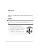
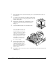
a
Attach the interface card
to the controller board.
b
Position the interface
card so that its I/O con-
nector slides into its
opening in the interface
panel and that its 80-pin
connector aligns with
the 80-pin connector on
the controller board.
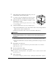
c
Gently press the inter-
face card down until its connector
is fully seated and the card is secured
by the plastic support post(s).
Attention
Make sure that the connectors on the interface card and controller board are
properly aligned. Damage to the interface card and/or controller board could
result if the pins are misaligned.
4
Secure the interface card to the interface panel with the two screws you
removed earlier.
5
Reinstall the controller board.
Gently slide the controller board into the printer until it is fully seated, and then
tighten the five screws.
6
Reconnect all interface cables.
7
Reconnect the power cord, and turn on the printer.
5"
In compliance with UL guidelines, “The appliance inlet is considered to be the main
disconnect device.”
8
Print a startup page.
Check that the startup page lists the interface (Optional NIC) just installed under
“Options.”
IIIIIIIIIIIIIIIIIIIIIIIIIIIIIIIIIIIIIIIIIIIIIII IIIIIIIIIIIIIIIIIIIIIIIIIIIIIIIIIII IIIIIIIII
................................................ ........................ ..........
................................................ ........................ ..........
................................................ ........................ ..........
................................................ ........................ ..........