
Laser Printer Service Manual


magicolor 330 - Base Engine Service Manual 4-5
Primary Fault Isolation Procedures
4.1 - Inoperative Printer, continued
Step Actions and Questions Yes No
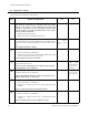
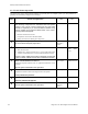
7
CONTROLLER PWB CHECK
1. Switch off the Main Switch.
2. Remove the Controller PWB (RRP 9.129).
3. Switch on the Main Switch.
Does the printer go into warm-up?
Replace the
Controller
PWB (9.129)
with a new one
Go to step 8
8
Replace the MCU PWB (RRP 9.123)
Does the printer go into warm-up?
Problem solved Go to step 9
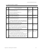
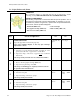
9
LVPS LOADING CHECK
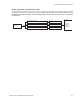
1. Disconnect P35 from the LVPS.
2. Measure the voltage between P33-3 on the LVPS and Frame
Ground, and between P32-11 on the LVPS and Frame Ground.
Is there +5VDC between P33-3 and Frame Ground, and is there
+24VDC between P32-11 and Frame Ground?
Replace the
Fuser Assem-
bly (RRP 9.80)
Go to step 10
10
LVPS LOADING CHECK
1. Disconnect P32 and P33 from the LVPS.
2. Measure the voltage between P33-3 on the LVPS and Frame
Ground, and between P32-11 on the LVPS and Frame Ground.
Is there +5VDC between P33-3 and Frame Ground, and is there
+24VDC between P32-11 and Frame Ground?
Go to step 11 Replace the
LVPS (RR P
9.119)
11
MCU PWB LOADING CHECK
1. Reconnect P32 and P33 to the LVPS.
2. Refer to Section 12 Wiring Diagrams and one by one disconnect
components that are connected to the MCU PWB.
3. Measure the voltage between P33-3 on the LVPS and Frame
Ground, and between P32-11 on the LVPS and Frame Ground.
Do you eventually measure +5VDC between P33-3 and Frame
Ground, and +24VDC between P32-11 and Frame Ground?
Replace the
component that
loads down the
LVPS.
Replace the
MCU PWB
(RRP 9.123)