E HARDWARE MANUAL 9222-2887-11 P-A208
BEFORE YOU BEGIN Thank you for purchasing this Minolta product. Please take the time to read through this instruction manual so you can enjoy all the features of your new scanner. This manual contains information regarding products introduced before September, 2002. To obtain compatibility information for products released after this date, contact a Minolta Service Facility (www.minoltasupport.com). This product is designed to work with accessories manufactured and distributed by Minolta.
FOR PROPER AND SAFE USE Read and understand all warnings and cautions before using this product. WARNING • Use only within the voltage range specified on the unit. Inappropriate current may cause damage or injury through fire or electric shock. • Do not disassemble this product. Electric shock may cause injury if a high-voltage circuit inside the product is touched. Take the product to a Minolta Service Facility when repairs are required.
TABLE OF CONTENTS This manual contains information specific to this model scanner. This includes hardware setup and use as well as notes about software operation for this model scanner. See the supplied DiMAGE Scan Utility software manual for information on the installation and operation of the scanner software. System requirements......................................................................................................5 Names of parts .........................................................
SYSTEM REQUIREMENTS The computer and the operating system must be guarantied by the manufacturer to support IEEE 1394 (FireWire), or SCSI interface. Check the Minolta web site for the latest compatibility information: Europe: http://www.minoltasupport.com North America: http://www.minoltausa.com. PC / AT compatible computers Macintosh SCSI: Pentium 166MHz or later processor. IEEE 1394: Pentium II or later processor. SCSI: PowerPC 604 or later FireWire: PowerPC G3 or later.
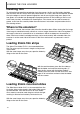
NAMES OF PARTS Front door Indicator lamp SCSI ID switch Eject button Power switch Dip switch IEEE 1394 (FireWire) ports AC terminal Film masks SCSI ports Slide Mount Holder (p. 10) Film attachments 35mm Film Holder (p. 10) Universal Holder (p.
SCANNER SETUP Removing the optics locking screw Before the scanner can be used, the optics locking screw on the bottom panel of the scanner must be removed with a flat-head screwdriver. The locking screw is necessary to transport the scanner. Place the screw in the storage position toward the front of the scanner body for future use. Transporting the scanner To prevent damage when transporting the scanner, the optics locking screw must be used.
SCANNER SETUP Connecting the SCSI cable The scanner is supplied with an ultra SCSI D-sub half-pitch 50-pin cable. Contact your dealer if a different cable is required. The computer and all peripheral devices must be off before connecting the scanner. The terminator dip switch on the back of the scanner eliminates the need for an external terminator.
Connecting the IEEE1394 (FireWire) cable The scanner is supplied with an IEEE 1394 (FireWire) cable. Up to 63 devices can be attached to a computer using this interface. However, the number of devices is limited to 16 when using a daisy-chain configuration. The computer and all peripheral devices must be off before connecting the scanner. Set dip switch number 4 to the off position to active the IEEE ports. Switch 4 must be moved to the on position if a SCSI cable is used.
LOADING THE FILM HOLDERS Handling film To achieve the best possible reproduction from the scanner, the film and film holder should be free from dust and dirt. Always work with processed film in a clean, dust-free environment. Handle film by the edges or mount to prevent fingerprints and dirt marring the image area. Special lint free gloves are available from photographic equipment retailers for film handling as well as antistatic cloths, brushes, and blowers for removing dust.
With the emulsion down, place the slide mounts sideways into the holder. The mount must be oriented as illustrated otherwise the top and bottom of the image will be cropped. Carefully close the cover until the latch clicks. See page 15 for instructions on how to load the holder into the scanner. When the slide mount holder is in the scanner, the last slide can be removed and a new slide inserted without ejecting the holder.
LOADING THE FILM HOLDERS Using the standard attachment The standard attachment is equipped with glass to hold the film flat. A set of five masks are provided for standard formats: 6X4.5, 6X6, 6X7, 6X8, and 6X9. See page 11 for instructions on how to insert the attachment into the Universal Holder. To open, press the latch on the attachment and lift the cover. Slide the tabs of the appropriate mask into the corresponding slots on each side of the attachment hinge.
With the emulsion down, place the film on the attachment. Align the frame with the attachment aperture. Carefully close the cover until the latch clicks. See page 15 for instructions on how to load the holder into the scanner. Multi-format Set HS-P1 (sold separately) The multi-format attachment allows non-standard film sizes to be scanned. The set includes the multi-format attachment cover (1), the multi-format attachment base (2), and a set of three masks (FM-P2)(3).
LOADING THE FILM HOLDERS With a straight edge and sharp knife, cut the aperture for the film from one of the masks. The aperture should be the same dimensions as the image area, not the film size; the mask should separate the film from the glass base of the attachment to prevent newton rings, and the aperture should only show the image area to eliminate flare from the surrounding clear film. Slide the tab of the mask into the slot on the side of the Universal Holder.
Loading a film holder into the scanner Before using the scanner, install the DiMAGE Scan Utility; see the software instruction manual. Turn on the scanner and then start the computer. Launch the DiMAGE Scan Utility before inserting the film holder. Do not insert the film holder into the scanner while the DiMAGE Scan Utility is launching or the scanner is initializing (the indicator lamp blinks during this period). Insert the film holder into the scanner in the direction indicated by the white arrow.
SCANNER NOTES Easy Scan Utility The Easy Scan Utility software is a simple scanning interface designed for individuals with no image processing or DTP experience. This software is not compatible with this scanner. The DiMAGE Scan Utility’s custom wizard can be used to automate the scanning workflow, see the software instruction manual. About the DiMAGE Scan Utility Prescan size can be selected in the preferences dialog box with this scanner model.
Windows 98, 98SE, 2000 professional, XP, and Macintosh Quit the DiMAGE Scan Utility. Confirm that the scanner indicator lamp is not blinking. Turn the scanner off and then disconnect the cable. Windows Me To disconnect the scanner, quit the DiMAGE Scan Utility. Left click on the unplug-oreject-hardware icon located on the task bar. A small window will open indicating the device to be stopped. Click on the small window to stop the device. The safe-to-remove-hardware window will appear. Click OK.
SCANNER NOTES Digital ICE3 system requirements Digital ICE3 is a collection of powerful image-processing tools. To make use of the Digital ROC and GEM functions, the following system requirements must be met: PC/AT compatible computers Interface SCSI IEEE 1394 SCSI or IEEE 1394 Minimum system requirements Hard disk space RAM CPU 35 mm 1.2GB 128MB 8 bit Multi-format 35 mm 2GB 6X9 4GB Pentium 166MHz or later 2GB 256MB 35 mm 16 bit Multi-format 35 mm 3GB 6X9 6GB 35 mm 1.
Scanner resolution The maximum resolution of this scanner is 4800 X 4800 dpi. The maximum optical resolution varies with the format of the film: 35 mm film - 4800 X 4800, medium-format film - 3200 X 4800. Scans of medium-format film can have a final resolution of 4800 X 4800 dpi through interpolation. The minimum resolution is 300 dpi for 35mm and 200 dpi for medium-format film.
JOB FILE LISTS Jobs can be used to make scan settings based on the final use of the image. See making-thefinal-scan section in the DiMAGE Scan Utility manual. The following charts list the parameters of the scanner’s Job files: 35mm Category Job name Input res. Output res. Mag. Input size Unit W 4800 Lock (input) H Output size W 37.08 25.02 1.460 0.
6 X 4.5 Category Job name Input res. Output res. Mag. Unit Lock (input) Input size W 3200 H Output size W 42.67 56.58 1.68 2.23 Lock (output) H Input pixels W H 5376 7128 Default Default 800 300 266 pixel 1344 1782 OFF 1344 1782 OFF 1344 ColorLaserPrinter A3Full 4454 600 742 mm 40.03 56.6 OFF 297 420 ON 7015 A4Full 3150 600 525 mm 40 56.57 OFF 210 297 ON 4960 7015 A4Half 2227 600 371 mm 39.89 56.
JOB FILE LISTS 6X6 Category Job name Input res. Output res. Mag. Unit Lock (input) Input size W 3200 H Output size W 56.58 56.58 2.23 2.23 Lock (output) H Input pixels W H 7128 7128 Default Default 800 300 266 pixel 1782 1782 OFF 1782 1782 OFF 1782 ColorLaserPrinter A3Full 3150 600 525 mm 56.57 56.57 OFF 297 297 ON 7015 7015 A4Full 2227 600 371 mm 56.6 56.6 OFF 210 210 ON 4960 4960 A4Half 1570 600 261 mm 56.71 56.
6X7 Category Job name Input res. Output res. Mag. Unit Lock (input) Input size W 3200 H Output size W 70.10 56.58 2.76 2.23 Lock (output) H Input pixels W H 8832 7128 Default Default 800 300 266 pixel 2208 1782 OFF 2208 1782 OFF 2208 ColorLaserPrinter A3Full 3595 600 599 mm 70.12 49.58 OFF 420 297 ON 9921 A4Full 2542 600 423 mm 70.21 49.65 OFF 297 210 ON 7015 4960 A4Half 1798 600 299 mm 70.23 49.
JOB FILE LISTS 6X8 Category Job name Input res. Output res. Mag. Unit Default ColorLaserPrinter Photosensitive Default 800 300 266 pixel Lock (input) Input size W 3200 H Output size W 77.15 56.58 3.04 2.23 2430 1782 Lock (output) H OFF 2430 Input pixels W 1782 OFF H 9720 7128 2430 1782 A3Full 3200 600 533 mm 77.2 55.72 OFF 411.48 297 ON 9720 7015 A4Full 2310 600 385 mm 77.14 54.55 OFF 297 210 ON 7015 4960 A4Half 1633 600 272 mm 77.21 54.
6 X 9 and Multi-format 6 X 9 Category Job name Input res. Output res. Mag. Unit Lock (input) Input size W 3200 H Output size W 83.82 56.58 3.30 2.23 Lock (output) H Input pixels W H 10560 7128 Default Default 800 300 266 pixel 2640 1782 OFF 2640 1782 OFF 2640 1782 ColorLaserPrinter A3Full 3150 600 525 mm 80 56.57 OFF 420 297 ON 9921 7015 A4Full 2227 600 371 mm 80.05 56.6 OFF 297 210 ON 7015 4960 A4Half 1570 600 261 mm 80.46 56.
TROUBLESHOOTING This section covers minor problems with scanner operation. For major problems or damage, or if a problem continues to reoccur frequently, contact your dealer or a Minolta service facility. Symptom or message Solution The computer will not start up after connecting the scanner. Turn off the computer and any devices in the SCSI or IEEE (FireWire) chain. Check the scanner cable and power cord are connected correctly and the dip switches are in the correct position for the interface.
Checking software installation – Windows If the scanner was connected to the computer before the DiMAGE Scan Utility was installed, the computer may not recognize the scanner unit. Windows 2000 Professional and XP users should log on with the administrator privilege. With Windows 2000 Professional and XP, the “Digital signatures not found” message may appear when the computer first detects the scanner. The additional message “Installing hardware...
TROUBLESHOOTING Technical support Please contact your dealer for information regarding installation, SCSI or IEEE 1394 interface recommendations, or application compatibility. If your dealer is unable to help you, contact an authorized Minolta service facility listed on the back cover. Please have the following information ready when calling Minolta technical support: 1. The name and model of your computer. 2. The available application RAM. 3. Other connected IEEE 1394 or SCSI devices. 4.
IMAGE DATA SHEET Image: Date: Film: Exposure: Image processing Image-correction Job: Brightness, contrast, & color balance palette Brightness: Hue, saturation & lightness palette Hue: Contrast: Red: Filtration: Unsharp mask Selective-color palette Amount: Cyan: R/ G/ B/ C/ M/ Y/ Saturation: Radius: Magenta: R/ G/ B/ C/ M/ Y/ Lightness: Threshold: Yellow R/ G/ B/ C/ M/ Y/ Shadow: Black: R/ G/ B/ C/ M/ Y/ Green: Blue: Digital ICE: Exposure control Exposure-control setting file:
TECHNICAL SPECIFICATIONS Type: Scan method: Light source: Imaging sensor: Maximum scan resolution: Scanning dimensions: Multi-format film scanner Fixed film, moving sensor, single-pass scan Three wavelength cold cathode fluorescent Three-line RGB CCD with 7,260 pixels per line 4,800 X 4,800 35 mm - 25.0 X 37.1 mm Medium format - 56.58 X 83.82 mm Negative or positive, color or monochrome 35 mm, 120, and 220 film (6X4.5, 6X6, 6X7, 6X8, 6X9) Input - 16 bit, output - 8 or 16 bit 4.
MINOLTA HISTORY Why does a manufacturer of high-quality 35 mm cameras produce a medium-format scanner? This is not as strange as it may seem. After all, Minolta’s first product was a roll-film camera. The Nifcarette folding camera started the company in 1926. Minolta was also the first Japanese manufacture to make a twin lens reflex (TLR) camera in 1937, the Minolta Flex. We continued to design and produce medium-format cameras until the mid 60s. The last TLR released by Minolta was the 1965 Autocord CdS.
© 2002 Minolta Co., Ltd. under the Berne Convention and the Universal Copyright Convention.