eRDA-850LW series indoor bicycle trainer instructions manual -1-
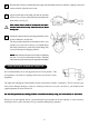
F-2 F-4 SCHEMATIC F-4 F-8 R8-1 Screw-M F-9 F-1 F-7 SR-13 ER-3 SR-12 SR-12 ER-1 ER-10 M8-3 ER-7 M8-4 M8-4 ER-8 ER-2 SR-5 Screw-L ER-12 SR-7 ER-4 SR-8 ER-5 ER-11 ER-14 ER-13 Screw-S Screw w/ washer ER-9 ER-15 ER-6 Screw-M F-1 : F-2 : F-4 : F-7 : F-8 : F-9 : R8-1 : M8-3 : M8-4 : SR-5 : SR-7 : SR-8 : SR-12 : SR-13 : Coupling (Right) Coupling (Left) Coupling Cover (move side) Hub Handle (3/8” thread) Wheel Position Adjust Knob Hub Nut Protector (Grommet) RDA-850 Main
IMPORTANT NOTES • • • • • • Read all instructions carefully before use. Some assembly required. Keep the manual handy at all times. Do NOT use trainer for any other purpose than instructed. The trainer is manufactured to precise standards. Disassembly may void your warranty. "Magturbo" and “RDA” are the trademarks of Minoura Co.,Ltd. and may not be copied. WARNINGS ! ! Use two-wheeled bicycles only. Tandems may be used if balanced correctly.
HOW TO SETUP YOUR E-RDA850 TRAINER 1 Open the frame support legs and fit the rubber feet at the correct angle so the base is in full contact with the floor. Do NOT remove the round metal plates from inside the rubber feet when fitting. Ensure the rubber foot caps are facing outwards as incorrect fitting may compromise the stability of the trainer.
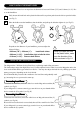
Hold the bike firmly by hand and turn the right side hub handle clockwise until the coupling comes into contact with the right side skewer nut. 6 Adjust each height of the Mag unit and the assistant roller to fit to your rear wheel perfectly and tighten the bolts firmly. (see Fig. G) ! 7 (Fig. G) Each rubber roller is made to contact the rim ONLY. Contact with the tire may cause the tire to burst during use. Adjust the wheel position by checking the double-circle position indicators on both side.
HOW TO INSTALL THE REMOTE LEVER You can install the remote lever on anywhere the diameter is between 22.2mm (7/8”) and 31.8mm (1-1/4”) like as on the handlebar. 1 Fully loosen the knob bolt on the plastic holder until it stops then push down the bolt to open the holder. (see Fig. J) 2 Place the holder onto the handlebar, shut the holder, and pull up the bolt then tighten it. (see Fig. K) Shim (Fig. J) (Fig. K) Depends on the diameter of your handlebar, you must adjust the shim as follows; • 22.
! To make any adjustment to the unit, make sure you are off the bike, and that the trainer has come to a complete stop and that nothing is still moving. (Fig. N) TROUBLE SHOOTING YOUR REMOTE SHIFTER UNIT If you cannot shift to either the lowest (L) or the highest (H) position, it is possible that the inner wire of the remote shifter cable is too long and the wire tension is loose. If so, please adjust the tension with the following steps. 1 Set the remote shifter lever at “H” position.
CHANGING YOUR NON-REMOTE TRAINER TO A REMOTE TRAINER You can change your dial type Mag unit to be a remote controlable one. Of course, the opposite way is possible. 1 Remove the dial lever by removing two small screws. 2 Remove the bottom spring holder by removing two medium screws and remove the inside spring. You should keep a memo where the bottom pin of the spring was installed for returning to dial type again. 3 Change the spring position as shown in the Fig. P.