ED6000T & ED6200T Parallel Redundant ON-LINE SERIES User’s Manual Para Systems, Inc. 1455 LeMay Drive Carrollton, TX 75007 Phone: 1-972-446-7363 Fax: 1-972-446-9011 Internet: minutemanups.com UPS Sizing: sizemyups.
Table of Contents 1 Important Safety Instructions................................................... 2 1.1 An Important Notice............................................................... 2 1.2 Life Support Policy ................................................................ 3 1.3 FCC Notice............................................................................ 3 2 Product Introduction ................................................................. 4 2.1 System Overview..........................
1 Important Safety Instruction 1.1. An Important Notice 1.1.1 To ensure safety in all applications where a UPS system is hardwired to the electrical supply the UPS must be installed by a Qualified Electrical Contractor. 1.1.2 The UPS has its own internal energy source (battery). If the UPS is switched on when there is no AC power is available, there could be voltage at the output terminals. 1.1.3 Servicing of the UPS system must be performed by Qualified Service Personnel ONLY.
2 Product Introduction 2.1. System Overview This On-Line UPS protects computers, servers, internetworking, and telecommunications equipment from blackouts, brownouts, overvoltages, and surges. This On-Line UPS converts the input AC to DC and then back to a True Sine Wave AC output. The True Sine Wave output is regulated within 2% of the nominal output voltage.
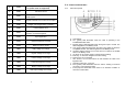
15 ON and Alarm Silencer Switch 32 Er06 Output Short Circuit 16 OFF Switch 33 Er08 DC Bus high-voltage-level abnormal 17 Previous Page or Setting Change 34 Er09 DC Bus low-voltage-level abnormal 18 Next Page 35 Er10 Inverter Over-current 19 Special Function Log in /out 36 Er11 UPS Overheated 20 Enter or Reconfirmed 37 Er12 Inverter Overload Utility Input Normal LED 38 Er13 Charger Failure or Abnormal 21 39 Er14 Fan Failure 22 Bypass Input Normal LED 40 Er15 Wrong pro
2.4. Controls and Indicators 48 Er24 Bypass Input found when running on CVCF mode (CVCF mode not supported) 49 Er26 PFC Over-current 50 Er27 The UPS must be operated in normal mode in parallel system 51 Er28 Bypass Overload Time out and cut off output.
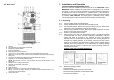
2.5. Rear Panel 3 Installation and Operation (QUALIFIED SERVICE PERSONNEL ONLY) Be sure to read the Installation Placement and all of the CAUTIONS and the WARNINGS before installing the UPS system. Packages that are crushed, punctured, or torn such that the contents are revealed should be set-aside in an isolated area and be inspected by a qualified person. If the package is deemed to be not usable, immediately contact the freight carrier and the place of purchase.
3.2. Installation Placement 3.4. Installation of the Caster Covers This UPS system is intended to be install in a temperature controlled environment that is free of conductive contaminants. Select a location, which will provide good air circulation for the UPS at all times. Keep at least 12 inches (30cm) clearance from the rear panel of the UPS to the wall. Avoid locations near heating devices, water or excessive humidity, or where the UPS is exposed to direct sunlight.
3.5. Wiring the Input and Output Connections (Qualified Electrical Contractor Only) 3.5.1 A Qualified Electrical Contractor must perform the hardwiring when connecting the Input and Output wires to the terminal block on the ED6000T UPS. Apply 22.1lb-in of torque force when connecting to the terminal blocks. The Input and Output of the UPS MUST be Hardwired. 3.5.1.1.2 Configuration # 1: Output: Two 120VAC 3KVA circuits (3KVA max load per circuit). Total combined output load not to exceed 6KVA. 1.
3.5.1.1.4 Configuration # 3: Output: One 208VAC 6KVA circuit. Total output load not to exceed 6KVA. 1. Connect a jumper wire from L22 to N21. 2. Circuit1 (208VAC): L23 - L1, N22 - L2, G2 - Ground. 3.5.1.1.5 Configuration # 4: Output: One 240VAC 6KVA circuit. Total output load not to exceed 6KVA. 1. Connect a jumper wire from L22 to N21. 2. Circuit1 (240VAC): L21 - L1, N22 - L2, G2 - Ground. 16 3.5.1.1.6 Configuration # 5: Output: Two 120VAC circuits (3KVA max load per circuit).
3.5.2 A Qualified Electrical Contractor must perform the hardwiring when connecting the Input and Output wires to the terminal block on the ED6200T UPS. Apply 22.1lb-in of torque force when connecting to the terminal blocks. The Input and Output of the UPS MUST be Hardwired. 3.6. Operation and Setup Instructions 3.6.1 Startup in the Normal Mode 3.6.1.1 Switch the Utility power circuit breaker (at the service panel) to the On position. 3.6.1.
3.6.1.6 The UPS will perform another self-test and the LCD display will change from drawing C to drawing D. During the self-test the UPS will switch to the Battery mode for approximately 4-seconds, then the LCD display will change from drawing D to drawing E1. Once the UPS successfully passes the self-test the LCD will display drawing F. If the UPS fails the self-test the LCD will display drawing E2 then the LCD will display an error code or error status. See Section 2.
I K * It shows the UPS is providing power to the “load”. 3.6.3 * It shows the input frequency from the Bypass Input. Measured Values detected by UPS 3.6.3.1 If you would like to check the measured values detected by the UPS, and scroll up keypads.
P R1 * It shows the Internal Temperature of the UPS System. 3.6.4 * It shows the Self-test is “Disabled”. UPS Default Data and Special Function Features 3.6.4.1 Once the UPS has successfully started up, press the Special Function keypad to change the LCD display screen to drawing Q1. R2 * It shows the Self-test is “Enabled”. Q1 * It shows the Buzzer is “Enabled”. S1 * It shows the Bypass Voltage is adjusted to the lower limit. Q2 * It shows the Buzzer is “Disabled”. 3.6.4.
U Y * It shows that this UPS is the first UPS in the parallel systems. * It shows the Inverter Output Voltage setting. keypad to change the default setting. The settings 3.6.4.3 Press the scroll up includes Buzzer ON (as drawing Q1), or Buzzer OFF (as drawing Q2, Alarm silence for UPS Warning) and self-test OFF (as drawing R1) or Selftest ON (as drawing R2). The UPS will execute battery test for 10-seconds.
keypad 3.6.5.10 When all of the setting changes are complete, press the enter to save all the changes. Then the LCD screen will display drawing Z, then the LCD screen will change to drawing AA to confirm the changes. If you do not want to save the changes press the “OFF” keypad for 5seconds, then the LCD screen turns to Drawing AA, which means your changes were not saved. 3.6.5.11 Turn Off the input circuit breaker on the rear panel of the UPS module. 3.6.5.12 The changes to the Settings are complete.
3.6.8.1.12 Press and hold the On Switch (on the front panel of the UPS) for approximately 3-seconds, then release. The audible alarm will sound 2beeps. The UPS will perform its normal startup test. Once the startup is complete the UPS will be in the normal On-Line mode. NOTE: If the Maintenance Bypass Procedure is not followed in the correct order and step-by-step the UPS and/or the connected equipment could be damaged.
6 Troubleshooting Guide 7 Replacing the Batteries If the UPS malfunctions, check the followings: a. Is the wiring of the input and the output correct? b. Is the input voltage within the acceptable window of the UPS? If items a. and b. above are correct then proceed with the following chart. If the problem persists, see Obtaining Service. Situation UPS Red Fault LED lights up Check Items Solution Check the error code shown on the LCD screen 1.
7.1. Battery Replacement Procedure (QUALIFIED SERVICE PERSONNEL ONLY) This UPS system does not have Hot-swappable batteries. The UPS system must be turned Off to perform the Battery Replacement. 7.1.1 Turn Off all the equipment that is connected to the UPS. 7.1.2 Press the Off switch on the front panel of the UPS for approximately 5seconds. 7.1.3 Turn the input circuit breaker on the rear panel of the UPS to the Off position. 7.1.
7.1.21 Looking from the front of the UPS on the left-hand side (FIG. 4), disconnect the battery negative (Black) wire. Place a piece of electrical tape over the end of battery negative (Black) wire. 7.1.22 Disconnect battery jumper “A” and place a piece of electrical tape over the end of battery jumper wire “A”. 7.1.23 Disconnect all of the battery jumper wires. 7.1.24 Remove the battery-retaining bracket retaining screws. 7.1.25 Remove the battery-retaining brackets. 7.1.
8 Specifications MODEL Topology Maximum Power Capacity BATTERY ED6000T ED6200T (Has an internal Galvanic isolation step-down transformer) Double Conversion On-Line, True Sine Wave 6000VA/4200Watts INPUT Number of Phases Nominal Voltage Acceptable Input Voltage Voltage Range Power Factor Correction Frequency Limits Low Voltage Transfer Point High Voltage Transfer Point Protection Single (1Ø 2W +G) 208VAC 0 - 300VAC 160* - 280VAC >98% at Full Load 50/60Hz +/-5Hz autosensing 160V resets to utility power
9 Obtaining Service 9.1.1 9.1.2 9.1.3 9.1.4 10 Limited Product Warranty Use the troubleshooting section to eliminate obvious causes. Verify there are no circuit breakers tripped. A tripped circuit breaker is the most common problem. Call your dealer for assistance. If you cannot reach your dealer, or if they cannot resolve the problem call or fax MINUTEMAN Technical Support at the following numbers; Voice phone (972) 446-7363, FAX line (972) 446-9011 or visit our Web site at www.minutemanups.
Notes: 11 Declaration of Conformity Application of Council Directive(s): 89/336/EEC, 73/23/EEC Standard(s) to which Conformity is declared: EN62040-1-1, EN62040-2, EN61000-3-2, EN61000-3-3, UL 1778, cUL (CSA 22.2 no. 107.1) Manufacturer’s Name: Para Systems, Inc.