Entrust Series UPS User's Manual
English 1. Introduction 2 2. Controls and Indicators 6 3. Installation 7 4. Operation 10 5. Troubleshooting 12 6. Replacing the Battery 13 7. Obtaining Service 16 8. Specifications 17 9. Limited Product Warranty 19 A1.
English Thank you for purchasing this power protection product. It has been designed and manufactured to provide many years of trouble free service.
This symbol indicates "Equipment Grounding Conductor" CAUTION! Connect the UPS to a two pole, three wire grounding AC wall outlet. The receptacle must be connected to the appropriate branch protection (circuit breaker or fuse). Connection to any other type of receptacle may result in a shock hazard and violate local electrical codes. Do not use extension cords, adapter plugs, or surge strips.
English NOTICE: This equipment has been tested and found to comply with the limits for a Class B computing device in accordance with the specifications in Subpart J of Part 15 of FCC Rules and the Class B limits for radio noise emissions from digital apparatus set out in the Radio Interference of the Canadian Department of Communications. These limits are designed to provide reasonable protection against such interference in a residential installation.
As a general policy, we do not recommend the use of any of our products in life support applications where failure or malfunction of the product can be reasonably expected to cause failure of the life support device or to significantly affect its safety or effectiveness. We do not recommend the use of any of our products in direct patient care.
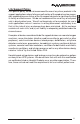
English 1. On/Off Button. 2. AC Mode (Green) LED. 3. On Battery (Yellow) LED. 4. Bad Battery/Overload/Fault (Red) LED. 5. Input power cord. 6. Surge Only output power receptacles. 7. The USB communications port is for UPS monitoring and control. 8. The RJ11/45 are used for phone/fax/modem and network protection. 9. Battery Backup and Surge output power receptacles. 10. Input circuit breaker.
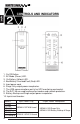
UPS Status Self-Test Green LED Yellow LED Red LED All LEDs cycle (each LED Blinks 1/1.5seconds) Alarm 1-Beep/5-sec AC Mode Normal Boost Buck Self low Battery Overload Off Off Off Off Off On 1-Blink/1.
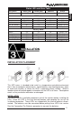
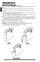
CONNECTING THE BATTERIES (QUALIFIED SERVICE PERSONNEL ONLY) English Please read all of the WARNINGS and CAUTIONS before attempting to connect the batteries. 1. Remove the UPS from the shipping box and set on a table or a bench top. 2. Remove the retaining screws from the bottom of the front panel of the UPS. (FIG. 1) 3. Gently push the top of the battery compartment cover inward and then slide the battery compartment cover off the UPS. (FIG. 2) 4.
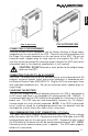
English FIG. 3: ETR700 FIG. 3: ETR1000/1500 CONNECTING YOUR EQUIPMENT Plug the mission critical equipment into the Battery Backup & Surge output receptacles on the rear panel of the UPS. Plug the non-critical equipment into the Surge Only output receptacles on the rear panel of the UPS. Do not use extension cords, adapter plugs or surge strips on the output of the UPS.
English PHONE/FAX/MODEM/NETWORK PROTECTION CONNECTION (OPTIONAL) Connect a 10/100 Base-T network, single line phone, fax or modem line to the RJ-11/45 modular connectors on the rear panel of the UPS. This connection will require another length of telephone cable (provided) or network cable. The cable coming from the telephone service or network system is connected to the port marked “IN”. The equipment to be protected is connected to the port marked "OUT".
On / Off Button Press and release the On/Off Button to turn the UPS on. The alarm will sound one beep and the LEDs will cycle while the UPS performs a five second internal self-test. Once the UPS has passed its internal self-test the UPS will provide an output and the load will be powered. Press and release the On/Off Button to turn the UPS off. The UPS will continue to charge the batteries whenever it is plugged into a wall outlet and there is an acceptable AC voltage present.
English Symptom Possible Cause What To Do UPS will not turn on On/Off/ button not pressed Press and release the On/Off button to start UPS UPS operates in Input AC circuit breaker is Reset circuit breaker by pressing the plunger back in.
English REPLACING THE BATTERY (QUALIFIED SERVICE PERSONNEL ONLY) Please read all of the WARNINGS and CAUTIONS before attempting to service the batteries. WARNING! This UPS contains potentially hazardous voltages. Do not attempt to disassemble the UPS beyond the battery replacement procedure. This UPS contains no user serviceable parts. Repairs and battery replacement must be performed by QUALIFIED SERVICE PERSONNEL ONLY. CAUTION: Do not open or mutilate batteries.
CAUTION: Replace batteries with the same number and type as originally inEnglish stalled in the UPS. These batteries have pressure operated vents. These UPSs contain sealed non-spillable maintenance-free lead acid batteries.
English FIG. 2 FIG. 1 FIG. 3: ETR500 FIG. 3: ETR700 FIG.
English IF THE UPS REQUIRES SERVICE 1. Use the TROUBLESHOOTING section to eliminate obvious causes. 2. Verify there are no circuit breakers tripped. A tripped circuit breaker is the most common problem. 3. Call your dealer for assistance. If you cannot reach your dealer, or if they cannot resolve the problem call or fax the Technical Support department at the following numbers; Voice phone (972) 446-7363, FAX line (972) 446-9011 or contact Minuteman UPS at mmsupport@minutemanups.com.
English SYSTEM SPECIFICATIONS ETR500 Model Number ETR700 ETR700p15 ETR1000 ETR1500 ETR1500p15 Line-Interactive, Simulated Sine Wave Topology Maximum Power Capacity 500VA 300W 700VA 420W 1000VA 600W 1500VA 900W INPUT Number of Phase Single (1∅ 2W +G) Nominal Voltage 120VAC Acceptable Input voltage 0 - 160VAC Voltage Range 90 - 150VAC Frequency Limits 50 or 60 Hz, +/-5Hz, autosensing Low Voltage Transfer Point 90V resets to Utility Power at 94V or higher High Voltage Transfer Point 15
BATTERY SYSTEM Battery Type Sealed, Non-Spillable, Maintenance Free, Value Regulated Lead Acid English Typical Recharge Time Typical Battery Life 8-hours from total discharge 3-5 years, depending on discharge cycles and ambient temp System Voltage 12VDC 12VDC 24VDC 24VDC 1-12V5Ah 1-12V7Ah 2-12V7Ah 2-12V9Ah Runtime: Half Load (minutes) 9 10 14 11 Runtime: Full Load (minutes) 2 3 4 3 Battery: Quantity/Rating SURGE PROTECTION AND FILTERING Surge Energy Rating 320 J Surge Current Capa
English Para Systems, Inc. (Para Systems) warrants this equipment, when properly applied and operated within specified conditions, against faulty materials (excluding the batteries) or workmanship for a period of three years from the date of purchase. Para Systems Inc. (Para Systems) warrants the batteries for a period of two years from the date of purchase.
A1. DECLARATION OF CONFORMITY English Application of Council Directive(s): 89/336/EEC, 73/23/EEC Standard(s) to which Conformity is declared: EN55022, EN55024 EN61000-6-1, EN61000-6-3 EN61000-4-5 Manufacturer’s Name: Para Systems, Inc.
English Notes: 21
Notes: English 22
Para Systems, Inc. 1455 Lemay Dr. Carrollton, TX 75007 Phone: 1-972-446-7363 Fax: 1-972-446-9011 Internet: minutemanups.com UPS Sizing: sizemyups.