MBK-E SERIES User's Manual
English MBK-E Series User's Manual 1. Introduction 2 2. Controls and Indicators 5 3. Installation 7 4. Operation 9 5. Troubleshooting 11 6. Replacing the Battery 12 7. Obtaining Service 15 8. Specifications 16 9. Configurable Parameters & Settings 17 10. Limited Product Warranty 18 11. Declaration of Conformity 20 © Copyright Para Systems, Inc.
English Thank you for purchasing a MINUTEMAN power protection product. It has been designed and manufactured to provide many years of trouble free service. IMPORTANT SAFETY INSTRUCTIONS SAVE THESE INSTRUCTIONS ! Please read this manual before installing your MBK-E Series UPS, models MBK550E, MBK750E, as it provides important information that should be followed during installation and maintenance of the UPS and batteries allowing you to correctly set up your system for the maximum safety and performance.
AC wall outlet. The receptacle must be connected to the appropriate branch protection (circuit breaker or fuse). Connection to any other type of receptacle may result in a shock hazard and violate local electrical codes. CAUTION! To reduce the risk of electrical shock in conditions where the load equipment grounding cannot be verified, disconnect the UPS from the AC wall outlet before installing a computer interface cable. Reconnect the power cord only after all signaling connections are made.
Receiving Inspection English After removing your MINUTEMAN UPS from its carton, it should be inspected for damage that may have occurred in shipping. Immediately notify the carrier and place of purchase if any damage is found. Warranty claims for damage caused by the carrier will not be honored. The packing materials that your UPS was shipped in are carefully designed to minimize any shipping damage.
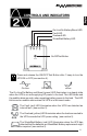
English On-Line/On-Battery/Boost LED Fault LED Overload LED Weak/Bad Battery LED On/Off/Test Button Press and release the ON/OFF/Test Button after 1 beep to turn the UPS ON or OFF (see section 4). On-Line On-Battery Boost The On-Line/On-Battery and Boost (green) LED illuminates in a steady state when the UPS is on and supplying AC power to the load. The LED blinks and the audible alarm sounds, when supplying battery power to the load.
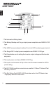
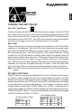
REAR PANEL English 1 9 2 3 4 8 5 6 7 1. The Information/Rating Label. 2. The Battery Backup and Surge output power receptacles are NEMA 5-15R type. 3. The USB Communications Interface Port is for UPS monitoring and control. 4. The Surge ONLY output power receptacles are NEMA 5-15R type. 5. The Dipswitches are for setting the Inverter output voltage and the transfer set points. 6. The input power cord has a NEMA 5-15P Plug. 7.
English INSTALLATION PLACEMENT The MBK-E series is intended to be install in a temperature controlled environment that is free of conductive contaminants. Select a location which will provide good air circulation for the UPS at all times. Avoid locations near heating devices, water or excessive humidity, or where the UPS is exposed to direct sunlight. Route power cords so they cannot be walked on or damaged.
WARNING! DO NOT plug Power Strips or Surge Protection Devices into English the ”Battery Backup” Receptacles on the UPS. Plugging Power Strips or Surge Protection Devices into the “Battery Backup” Receptacles may cause internal damage to the UPS, the Power Strip, or the Surge Protection Device. CONNECTING THE UPS TO AN AC SOURCE Plug the UPS into a two pole, three wire, grounded receptacle only. Do not use extension cords, adapter plugs, power strips or surge strips.
English TURNING THE UNIT ON/OFF ON / OFF / Test Button Press and release the ON/OFF/Test Button after one beep to turn the UPS ON and supply power to the load. The load is immediately powered while the UPS runs a two-second self test. Press and release the ON/OFF/Test Button after one beep to turn the UPS OFF. The UPS will continue to charge the batteries whenever it is plugged into an AC outlet and there is AC present.
ALARMS English ON BATTERY When the UPS is operating on the batteries, the On-Battery LED will blink and the audible alarm will sound once every 10-seconds. The alarm will stop once the UPS returns to the On-Line operation. LOW BATTERY WARNING The UPS will sound two beeps every five-seconds when the battery reserve runs low. This condition will continue until AC returns or the UPS shuts down from battery exhaustion.
English Symptom Possible Cause UPS will not turn on On/Off/Test button not pushed UPS operates in Input AC circuit breaker is battery mode only, tripped even though there is normal AC present Fault LED is illuminated Site Wiring Fault LED is illuminated The On-line/OnBattery LED is illuminated, but there is no output UPS has detected an internal fault Incorrect service wiring UPS does not provide expected runtime The batteries may be weak or at the end of useful service life The UPS is being controll
English REPLACING THE BATTERY (AUTHORIZED SERVICE PERSONNEL ONLY) The MBK-E Series UPS has an easy to replace hot-swappable batteries. Please read all of the WARNING and CAUTIONS before attempting to service the batteries. NOTE: If there is a power interruption while replacing the hot-swappable batteries, with the UPS on, the load will not be backed up. WARNING! This Uninterruptible Power Supply contains potentially hazardous voltages.
Model # MBK550E MBK750E Battery Model # 1-12V7Ah 2-12V7Ah Panasonic Part # LC-R127R2 LC-R127 Yuasa Part # NP 7-12 NP 7-12 BATTERY REPLACEMENT PROCEDURE PLEASE READ THE CAUTIONS AND WARNINGS BEFORE ATTEMPTING TO REPLACE THE BATTERIES Hot-swappable batteries mean that the batteries can be replaced without powering down the whole UPS system. NOTE: If there is a power interruption while replacing the hot-swappable batteries, with the UPS on, the load will not be backed up.
English 9. Disconnect the positive (red) wire from the battery positve terminal. 10. Disconnect the battery negative (black) wire from the battery negative terminal. NOTE: Use CAUTION, do not touch the battery positive wire to the battery negative wire. 11. Remove the battery bracket retaining screw and slide the battery bracket upwards. 12. Using the pull tab, pull the batteries out completely. DO NOT pull the batteries out by pulling the battery jumper wires. 13. Remove the battery jumper wire. 14.
English IF THE UPS REQUIRES SERVICE 1.Use the TROUBLESHOOTING section to eliminate obvious causes. 2.Verify there are no circuit breakers tripped. A tripped circuit breaker is the most common problem. 3.Call your dealer for assistance. If you cannot reach your dealer, or if they cannot resolve the problem call or fax MINUTEMAN Technical Support at the following numbers; Voice phone (972) 446-7363, FAX line (972) 446-9011 or visit our Web site at www.minutemanups.com the "Discussion Board".
English MODEL NUMBER Acceptable Input voltage Input voltage (AC Mode) MBK550E MBK750E 0 - 150VAC 120VAC setting (default):85-132VAC, Selectable: 75/80-132VAC 127VAC setting: 85-140VAC, Selectable: 75/80-140VAC 120VAC setting: 105-132VAC, 127VAC setting: 105-140V 50 or 60 Hz, autosensing Resettable circuit breaker 50 or 60 Hz, +/-6Hz 2-6 mS typical 750VA/450W 550VA/330W Default 120VAC (User selectable at 120/127VAC) 50/60 Hz, +/-.
English (These items may require optional software or hardware) Function UPS ID Battery install date Battery life in days Factory Default MBK-E User Choices Up to 64 characters to define the UPS Date of Date of battery manufacture replacement month/day/year XX/XX/XXXX Up to 5 1826 characters Description Use this function to uniquely identify the UPS in your network configuration Enter the current date when replacing batteries At first battery replacement, reset to reflect actual number of days experie
English Para Systems Inc. (Para Systems) warrants this equipment, when properly applied and operated within specified conditions, against faulty materials (excluding batteries) or workmanship for a period of three years from the date of purchase. Para Systems Inc. (Para Systems) warrants the batteries for a period of two years from the date of purchase.
LIMITED PRODUCT WARRANTY EXCEPT AS PROVIDED ABOVE, IN NO EVENT WILL PARA SYSTEMS BE LIABLE FOR DIRECT, INDIRECT, SPECIAL, INCIDENTAL, OR CONSEQUENTIAL DAMAGES ARISING OUT OF THE USE OF THIS PRODUCT, EVEN IF ADVISED OF THE POSSIBILITY OF SUCH DAMAGE. Specifically, Para Systems is not liable for any costs, such as lost profits or revenue, loss of equipment, loss of use of equipment, loss of software, loss of data, cost of substitutes, claims by third parties, or otherwise.
DECLARATION OF CONFORMITY English Application of Council Directive(s): 89/336/EEC, 73/23/EEC Standard(s) to which Conformity is declared: EN50091-1-1, EN50091-2 Manufacturer’s Name: Manufacturer’s Address: Para Systems, Inc.
English Notes: 21
English Notes: 22
Page do not print 23
Para Systems, Inc. 1455 Lemay Dr. Carrollton, TX 75007 Phone: 1-972-446-7363 Fax: 1-972-446-9011 Internet: minutemanups.com UPS Sizing: sizemyups.com PN - 34000227 Rev.