MCP Series Uninterruptible Power Supply MCP 1000, MCP 1000i MCP 2000, MCP 2000i MCP 3000, MCP 3000i User’s Manual
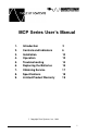
MCP Series User’s Manual 1. 2. 3. 4. 5. 6. 7. 8. 9. Introduction Controls and Indicators Installation Operation Troubleshooting Replacing the Batteries Obtaining Service Specifications Limited Product Warranty ã 2 6 10 12 14 15 17 18 19 Copyright Para Systems, Inc.
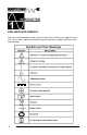
EXPLANATION OF SYMBOLS Some or all of the following symbols may be used in this manual or may appear on your unit. Please take a moment to familiarize yourself with these symbols and their associated meanings.
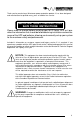
Thank you for purchasing a Minuteman power protection product. It has been designed and manufactured to provide many years of trouble free service. IMPORTANT SAFETY INSTRUCTIONS SAVE THESE INSTRUCTIONS Please read the manual before installing your MCP Series UPS as it provides the information that should be followed during installation and maintenance of the UPS and batteries allowing you to correctly set up your system for the maximum safety and performance.
Receiving Inspection After removing your Minuteman UPS from its carton, it should be inspected for damage that may have occurred in shipping. Immediately notify the carrier and place of purchase if any damage is found. Warranty claims for damage caused by the carrier will not be honored. The packing materials that your UPS were shipped in are carefully designed to minimize any shipping damage. In the unlikely case that the UPS needs to be returned to Minuteman, please use the original packing material.
Para Systems Life Support Policy As a general policy, Para systems Inc. (Para Systems) does not recommend the use of any of its products in life support applications where failure or malfunction of the Para Systems product can be reasonably expected to cause failure of the life support device or to significantly affect its safety or effectiveness. Para Systems does not recommend its products for use in direct patient care.
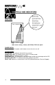
FRONT PANEL MCP Series 1000(i), 2000(i), and 3000(i) KVA front panel POWER SWITCH Press and release the power switch button to turn the unit on or off. LED INDICATORS ON LINE LED: This indicates that the AC line is normal. ON BATTERY LED: This indicates that the UPS is in battery mode. BYPASS LED: This indicates bypass is active. OVERLOAD LED: This indicates the connected load exceeds the rated output of the UPS. BATTERY LOW LED: This indicates low battery voltage in the UPS.
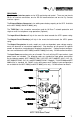
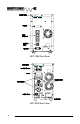
REAR PANEL The Computer Interface ports are for UPS monitoring and control. There are two female DB-9’s for interface connection, one for RS-232 communication and one for Dry Contact interface signals. The External Battery Connector is for adding more battery capacity to the UPS. Available on the MCP 2000(i) and MCP 3000(i) only. The TVSS Slot is for a modular connection used for 10 Base-T network protection and single or multi-line telephone surge protection (Optional).
MCP 1000i Rear Panel MCP 2000 Rear Panel 8
MCP 2000i Rear Panel MCP 3000 Rear Panel 9
MCP 3000i Rear Panel INSTALLATION PLACEMENT The safe and continuous operation of the UPS depends partially on the care taken by the user. Please note the following precautions: · Install the UPS in a temperature controlled, indoor environment that is free of conductive contaminants. · Select a location that will provide good air circulation for the UPS at all times. · Avoid locations near heating devices, water, or excessive humidity, or where the UPS may be exposed to direct sunlight.
COMPUTER INTERFACE CONNECTIONS Minuteman Power Management software and interface cables kits are used with these ports (software and cables are optional and available from Minuteman). Use only Minuteman or Minuteman approved interface cables with these UPS’s. Connect the interface cable to the DB-9 connector on the rear of the UPS (either RS-232 or Dry Contact). Secure the connector to the UPS via the screws on the connector housing.
NOTE: For hardwire I/O configurations for the MCP 2000(i) and the MCP 3000(i), units are considered fixed. When connecting equipment to hardwire I/O configurations ensure use of proper size gauge wires for all connections. CAUTION! DO NOT CONNECT A LASER PRINTER TO THE UPS UNLESS THE UPS IS RATED 2000VA OR GREATER. A LASER PRINTER DRAWS SIGNIFICANTLY MORE POWER WHEN PRINTING THAN AT IDLE AND MAY OVERLOAD THE UPS.
COMMUNICATION INTERFACE (1) RS232 NC----------------TXD--------------RXD--------------NC----------------Signal Ground--Pin2: Pin3: Pin5: 1 2 3 4 5 NC----------------NC----------------NC----------------NC----------------- 6 7 8 9 UPS transmits serial data to computer. UPS receives serial data from computer. Signal ground.
TROUBLESHOOTING CHART 14 Symtom Possible Cause What To Do UPS not on Power switch is in Off position. No incoming utility. Press On button. Check utility power. On Battery LED is illuminated even though there is normal AC present Input AC breaker is tripped. No incoming utility. Reset circuit breaker. Check input power connection. Fault LED is illuminated UPS has detected an internal fault. Turn UPS off, then on again. If Fault LED remains on contact Minuteman Technical Support.
REPLACING THE BATTERIES WARNING! This uninterruptible power source contains potentially hazardous voltages. It is recommended that you turn the UPS off and disconnect the input power cord from the receptacles prior to connecting or disconnecting the battery terminals. Only UPS’s that have external battery packs can be changed “HOT”, that is with your AC power connected to the unit, and while supplying power to your equipment.
· · · · · · · · If electrolyte contacts the skin, wash it off immediately with water. If electrolyte contacts the eyes, flush thoroughly and immediately with water. Seek medical attention. Determine if the battery is inadvertently grounded. If inadvertently grounded, remove source of ground. Contact with any part of a grounded battery can result in electric shock. The likelihood of such shock will be reduced if such grounds are removed during installation and maintenance.
IF THE UPS REQUIRES SERVICE 1. 2. 3. 4. 5. 6. 7. Use the TROUBLESHOOTING chart section 5 to eliminate obvious causes. Verify that no circuit breakers are tripped. A tripped circuit breaker is the most common problem. Call your dealer for assistance. If you cannot reach your dealer or if he cannot resolve the problem, call or fax Minuteman Technical Support at the following numbers: Voice phone (972) 446-7363, FAX line (972) 446-9011, e-mail: support@minuteman-ups.com.
NOTE: 230VAC Specs Shown In ( ) Acceptable Input Voltage Input Voltage (on-line operation) Power Factor Output Voltage (on-line operation) Transfer time Maximum Load Voltage regulation Nominal input frequency Input protection Frequency limits (on-line operation) THD Slew Rate Overload capacity Crest factor Efficiency On-battery Output Voltage On-battery frequency On-battery wave shape Protection Surge energy rating (one time 10/1000ms waveform) Surge current capability (one time, 8/20ms waveform) Surge resp
LIMITED PRODUCT WARRANTY Para Systems Inc. (Para Systems) warrants this equipment, when properly applied and operated within specified conditions, against faulty materials or workmanship for a period of three years from the date of original purchase by the end user. For equipment sites within the United States and Canada, this warranty covers repair or replacement of defective equipment at the discretion of Para Systems. Repair will be from the nearest authorized service center.
NOTES: 20
Para Systems, Inc. 1455 Lemay Dr. Carrollton, TX 75007 Phone: (972) 446-7363 Fax: (972) 446-9011 QuickFax Info Systems: 800-263-3933 www.minuteman-ups.