BP192RTXL BP240RTXL Battery Packs User's Manual Para Systems, Inc. 1455 Lemay Dr. Carrollton, TX 75007 Phone: 1-972-446-7363 Fax: 1-972-446-9011 Internet: minutemanups.com UPS Sizing: sizemyups.
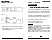
Table Of Contents 1. Introduction 2 2. Rear Panels 6 3. Installation 7 4. Operation 12 5. Replacing the Battery 12 6. Obtaining Service 18 7. Specifications 19 8.
Chapter 1: Introduction Thank you for purchasing this power protection product. It has been designed and manufactured to provide many years of trouble free service. Please read this manual before installing your BPRTXL Battery Pack, models BP192RTXL, BP240RTXL as it provides important information that should be followed during installation and maintenance of the Battery Packs and batteries allowing you to correctly set up your system for the maximum safety and performance.
NOTICE: This equipment has been tested and found to comply with the limits for a Class A computing device in accordance with the specifications in Subpart J of Part 15 of FCC Rules and the Class A limits for radio noise emissions from digital apparatus set out in the Radio Interference of the Canadian Department of Communications. These limits are designed to provide reasonable protection against such interference in a residential installation.
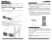
Chapter 2: Rear Panels Chapter 3: Installation INSTALLATION PLACEMENT This Battery Pack series is ONLY intended to be installed in an indoor temperature controlled environment that is free of conductive contaminants. DO NOT operate the Battery Pack in: extremely dusty and/or unclean areas, locations near heating devices, water or excessive humidity, or where the Battery Pack is exposed to direct sunlight. Select a location, which will provide good air circulation for the Battery Pack at all times.
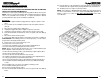
RACKMOUNT CONFIGURATION Use the included rackmount brackets and screws to mount the Battery Pack in a rack by following the steps below. USE CAUTION: These Battery Packs are extremely heavy. Use two or more people when installing the Battery Pack. CAUTION! DO NOT USE THE MOUNTING BRACKETS TO LIFT THE BATTERY PACK. The mounting brackets are ONLY for securing the Battery Pack to the rack. 1. Attach the rackmount brackets to the mounting holes on the side panels of the Battery Pack as shown below.
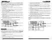
NOTE: If you are using more than one of these Battery Packs with the Endeavor 5-10KVA RT series UPS, the UPS must be configured so that the UPS will report the correct estimated runtime on the LCD screen and in the Power Monitoring software and/or the SNMP card. See the Power Monitoring software or the SNMP card’s User's Manual to configure the UPS. 1. The UPS MUST be in the off position. 2. The DC breaker(s) on the rear panel of the Battery Pack(s) MUST be in the off position. 3.
Chapter 4: Operation Replace the batteries and/or Battery Pack with the same number and type as originally installed. SYSTEM OVERVIEW These Battery Packs will extend the runtime capabilities of the UPS. These Battery Packs do not have internal chargers and are charged by the UPS to properly maintain the batteries. There is no maximum number for Daisy Chaining the Battery Packs, however the recharge time will increase exponentially for each Battery Pack added.
BATTERY REPLACEMENT PROCEDURE (QUALIFIED SERVICE PERSONNEL ONLY) PLEASE READ THE CAUTIONS AND WARNINGS BEFORE ATTEMPTING TO REPLACE THE BATTERY MODULES The batteries can be replaced without powering down the whole UPS system. NOTE: If there is a power interruption while replacing the batteries, with the UPS on, the load will not be backed up. To replace the batteries without powering down the UPS system start with step number 6. 24.
BP192RTXL (QUALIFIED SERVICE PERSONNEL ONLY) 1. Turn off the equipment that is plugged into the output receptacles of the UPS. 2. Press and release the On/Off/Test button on the front panel to turn the UPS off. 3. Disconnect the UPS from the utility power. 4. Unplug the equipment from the output receptacles of the UPS. 5. Unplug the computer interface cable from the rear panel of the UPS. 6. Turn off all of the DC circuit breakers on the rear panel of all of the Battery Packs. 7.
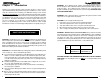
Chapter 6: Obtaining Service Chapter 7: Specifications IF THE BATTERY PACK REQUIRES SERVICE SYSTEM SPECIFICATIONS Model Number 1. Verify there are no tripped circuit breakers and that the batteries are good. A tripped circuit breaker and defective batteries are the most common issues. 2. Call your dealer for assistance.
Chapter 8: Limited Product Warranty Para Systems, Inc. (Para Systems) warrants this equipment, when properly applied and operated within specified conditions, against faulty materials or workmanship for a period of three years from the date of purchase. For equipment sites within the United States and Canada, this warranty covers depot repair or replacement of defective equipment at the discretion of Para Systems. Depot repair will be from the nearest authorized service center.