X R T Series Uninterruptible Power Supply User’s Manual 0
1
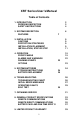
XRT Series User’s Manual Table of Contents 1. INTRODUCTION RECEIVING INSPECTION SAFETY INSTRUCTIONS 2. SYSTEM DESCRIPTION FEATURES 2 3 4 6 7 3. INSTALLATION CAUTIONS PROTECTION STRATEGIES INSTALLATION PLACEMENT INSTALLATION, STEP BY STEP 9 9 9 9 11 4. OPERATION FRONT PANELS ALARMS AND WARNINGS WARNING EVENTS OPTIONS 15 15 22 5. SYSTEM BATTERIES STORAGE INSTRUCTIONS BATTERY REPLACEMENT 6.
1. INTRODUCTION Thank you for purchasing the Minuteman XRT series of Uninterruptible Power Supplies. It has been designed and manufactured to provide many years of trouble free service. IMPORTANT! Please read this manual before installing your UPS as it provides the information to correctly set up your system for the maximum safety and performance.
organization. Therefore, these units do not meet the requirements for use in direct patient care.
RECEIVING INSPECTION After removing your Minuteman XRT UPS from its carton, it should be inspected for damage that may have occurred in shipping. Immediately notify the carrier and place of purchase if any damage is found. Warranty claims for damage caused by the carrier will not be honored. PLEASE SAVE THE PACKING MATERIALS! The packing materials that your UPS was shipped in are carefully designed to minimize any shipping damage.
IMPORTANT SAFETY INSTRUCTIONS SAVE THESE INSTRUCTIONS THIS MANUAL CONTAINS IMPORTANT SAFETY INSTRUCTIONS; Read this manual carefully before operating the UPS. All instructions and warnings should be followed during installation, operation and maintenance of the UPS. CAUTION: RISK OF ELECTRICAL SHOCK. HAZARDOUS LIVE PARTS INSIDE THIS POWER SUPPLY ARE ENERGIZED FROM THE BATTERY SUPPLY EVEN WHEN THE INPUT AC POWER IS DISCONNECTED.
INSTRUCTIONS IMPORTANTES CONCERNANT LA SÉCURITÉ CONSERVER CES INSTRUCTIONS. CETTE NOTICE CONTIENT DES INSTRUCTIONS IMPORTANTES CONCERNANT LA SÉCURITÉ. ATTENTION: RISQUE DE CHOC ÉLECTRONIQUE. CE BLOC D’ALIMENTATION COMPORTE DES PIECES SOUS TENSION DANGEREUSE ALIMENTÉES PAR LES PILES MEME LORSQU’IL EST DÉBRANCHÉ DU SECTEUR. ATTENTION: UNE BATTERIE PEUT PRÉSENTER UN RISQUE DE CHOC ÉLECTRIQUE, OU DE BRULURE PAR TRANSFERT D’ENERGIE. SUIVRE LES PRÉCAUTIONS QUI S’IMPOSENT.
2. SYSTEM DESCRIPTION The XRT series of Uninterruptible power supplies are based on an advanced true sinewave power system that filters and protects the electronic equipment from all types of power line problems. The various models provide from 600 VA to 2000 VA of power for voltage ranges of 120 VAC, 208 VAC and 240 VAC single phase 60 Hz. units, and 220 VAC through 240 VAC 50 Hz. units.
FEATURES Extended Battery Run Time All models of the XRT series may add multiple optional external XRTBP battery packs to extend the time that the units can provide power. UPS de-rating is not required for the additional battery packs. The XRT600 model contains an internal battery, whereas the higher power models require at least one XRTBP battery pack.
commands from the computer can control the UPS. The interface also allows a single switch to control the output power from the UPS so that a user-supplied Output Power Off switch or relay can immediately remove power from the load, or restore power once the problem has been corrected. See Remote Communications chapter for details of the communications port. Built in Self Test To insure the functionality of the UPS, there are four built-in self tests.
3. INSTALLATION CAUTION: Do not connect a laser printer to the UPS along with other computer equipment unless the UPS is rated at 2000 VA or higher. A laser printer periodically draws significantly more power than when idle, and may overload the UPS. Verify that the UPS can support the loads when the printer is in full operation (printing). PROTECTION STRATEGIES Minuteman UPS’s provide high quality protection from AC input power line disturbances to your equipment.
Do not place anything on the top of the UPS. Avoid locations near heating devices. Avoid locations near water or excessive humidity. Do not expose the UPS to direct sunlight. Route power cords where they cannot be walked on or damaged, or surrounded by other power cords or communication cables. Use common sense about placing the UPS where it cannot be accidentally bumped or turned over. The battery packs and UPS unit must be placed on a level, smooth surface and cannot be stacked more than 4 units high.
INSTALLATION, STEP BY STEP 1. Insure UPS Power switch is OFF. Place the optional XRTBP battery pack(s), if used, and XRT UPS in its final location. 2. When installing the XRT1000 and above UPS’s or the XRT600 with optional battery pack(s): a) Remove the self stick protective strip from the rear of the XRT600 (not required on XRT1000 , 1500, and 2000), and from the optional battery pack cable. b) Loosen the retainer screws on the rear of the UPS and drop the retainer bracket down.
3. If you have additional Transient Voltage Surge Suppression (TVSS) devices in your system, they may be connected to the Earth Ground lug at the rear of the UPS. This provides a single point connection to minimize the potential of surges to disrupt the system. This lug is connected to the SAFETY GROUND lead in the AC input power cable. 4. Plug in the UPS to the utility power outlet.
automatically run a self test and at the successful completion, provide power to the output receptacles and indicate “normal AC”. Certain faults will prevent the UPS from supplying power to your equipment and will cause an error status to be displayed and an audible alarm to sound. If this occurs see the TROUBLESHOOTING section. To insure the batteries are completely charged, it is a good idea to leave the UPS on for 8 hours before using it to run your system.
Front Panel Load Menu on LCD Screen If an alarm condition exists, the condition will be reported on the front panel. If no AC Power is present and the battery is charged, pressing the DC START switch for approximately 5 seconds will bring up the UPS in the inverter mode and provide power to the protected equipment from the battery.
4. OPERATION FRONT PANELS The operation of the UPS depends on which front panel is used. The following section explains the operation for the LED and the LCD front panels. LED Front Panel The top four LED’s (Green) provide 3 functions. • During normal AC operation: The top LED’s indicate a measure of load. • During battery mode: The top LED’s indicate the battery charge condition which indicates approximate battery power remaining. • During a fault condition: The top LED’s display an error code.
Switches The Power switch turns the unit on and off. To start the UPS when AC power is not available, press and hold the DC Start button for about 5 seconds. The Test/Alarm Silence Button The Test/Alarm Silence button allows you to run the quick self test when the UPS is in the normal mode. If an error was detected and you wish to reset the error display, press the Test/Alarm Silence button.
If the unit is being powered from the AC line, the percentage of actual load power available will be shown by the “ON-LINE xxx% Load” message. Otherwise, if the unit is being powered from the battery, “BACKUP xx.xV BAT” message is displayed. In either case, you may press the button under the “MENU” selection to step to the STATUS menu. Menu Flow Note: The “road-map” through the menu system is shown below. In each individual menu, pressing the “menu” button will take you to the next set of menus.
Status Menu The status menu allows you to read the parameters of the UPS according to the flowchart shown below. The button under the word “Scroll” will step you to the next selection and the button under the word “Menu” will step you to the TEST menu. Load 50% Menu Scroll Load 750VA Menu Scroll AC Input 120.0V Menu Scroll Input 60Hz Menu Scroll Load xxx% : Percentage of load compared to power rating of the unit. If the load shows greater than 100 percent, then the load is too high for the UPS.
Test Menu The Test menu allows you to select the user controlled test modes. The “Quick Test” mode will perform a test of all of the key parameters of the UPS, including operation from the battery. The “Test To Low Bat” selection will place the UPS in the battery power mode, and run until the battery voltage drops to the Low Battery Warning point. Test Menu Menu Scroll Select “scroll” to go to the various test choices. Quick Test Menu Yes Scroll Perform the 10 second Quick Test.
Setup Menu The Setup menu allows you to set some of the UPS operating parameters. The parameters that can be set include the following; Setup Menu Menu Scroll Note: At any step in the “Setup” menu, pressing the “MENU” selection will move you to the “Config” menu. Audio Alarm xxx Menu xxx Scroll Audio Alarm xxx : Turn the Audible Alarm on or off. If the Alarm is OFF, the beeper will NOT sound during an alarm condition. The normal condition is ON.
Config Menu The configuration menu displays the configuration of the UPS. This information is required when you contact Minuteman’s technical support. Pressing the “Menu” button will return to the “Mode Display” menu. Config Menu Menu Scroll Model XRTxxxx Menu Scroll Model XRTxxxx : Will display this XRT model number S/N xxxxxxxxxx Menu Scroll S/N xxxxxxxxxx : Serial number for this UPS Mfg Code xxxx Menu Scroll Mfg Code xxxx : Your XRT manufacturing code number XRT Vxx.xx Menu Scroll XRT Vxx.
ALARMS AND WARNINGS Alarms Conditions that may require immediate attention will be signaled by the UPS beeping it’s audible alarm. The following is a list of alarms the XRT UPS reports: On Battery (AC Fail) When the UPS has detected a condition that forces it to run from the battery, an alarm will sound every 30 seconds. The alarm stops when normal AC returns to the unit. Pressing the Test/Alarm Silence button on the XRT600 will silence this alarm.
WARNING EVENTS Line Voltage Regulation The UPS will warn you when the incoming utility power exceeds its normal limits. On the LED front panel the Voltage Regulator LED will light, indicating the incoming voltage is out of range. On the LCD front panel, you will see a “Low Voltage In” or “High Voltage In” message. In either case the audible alarm will not sound. Output Voltage Switching The Output of the UPS may be turned OFF or ON by any of three ways other than the power switch.
5. SYSTEM BATTERIES The batteries used in the XRT series of UPS’s and the XRTBP battery packs are sealed, maintenance-free, lead-acid batteries, with the electrolyte completely absorbed in the plates and separator material. For maximum battery life, battery temperature should be kept as cool as practical indoors. Expected average battery life is 5 years. The XRT units monitor the condition of the batteries and indicate when the batteries are low.
BATTERY REPLACEMENT It is recommended that you turn the UPS off and disconnect the input power cord from the receptacles prior to connecting or disconnecting the battery terminals. Only UPS’s that have external battery packs can be changed “HOT”, that is with AC power connected to the unit, and while supplying power to your equipment. If battery packs MUST be changed while power is on, they can ONLY be changed while the AC line is supplying power to the protected equipment.
6. TROUBLESHOOTING If your XRT UPS does not function as you expect or if you get an error code or message, please follow the chart outlined below before calling your dealer or Minuteman. Make note of each problem so that we may quickly troubleshoot and correct the problem. Please remember to have your model and serial number before calling. TROUBLESHOOTING SYMPTOM POSSIBLE CAUSE Front panel switch in off position. Rear panel circuit breaker tripped. No incoming utility. ACTION TO TAKE Turn on switch.
INITIAL ERROR MESSAGES As soon as the UPS is first turned on, it performs a series of self tests. If the self tests fail then the UPS will report the failure and display the fault. If the self test passes, but the UPS was shut down previously due to a fault, the previous fault code or message will be displayed. This feature allows you to determine why the UPS shut down.
The LCD reporting screen in the XRT1000 and above UPS’s allows much more flexibility in communicating faults to you, and therefore has two classes of fault messages. The first occurs when the unit is initially turned on as explained above, and the second is if a fault is detected during normal operation or testing.
OPERATING FAULTS If, during operation, a fault is detected the XRT UPS will sound the alarm beeper and display the fault cause on the front panel. If you have disabled the alarm beeper, the fault will still be displayed. In the XRT600 UPS the upper four LED’s will be turned on according to the chart provided earlier. In the XRT1000 and above, the LCD screen will show the fault message.
SELF TEST To have the XRT600 UPS perform a 10 second self test, press the Test/Alarm Silence key. This will perform the self test and report any errors to the LED display. A successful self test is indicated by the normal AC LED being lit. For the XRT1000 and above units, select the TEST MENU on the LCD screen and then select the QUICK TEST. The screen will report “TESTING” until the completion of the self test.
7. OBTAINING SERVICE If the UPS requires service: 1. Use the TROUBLESHOOTING section 6 to eliminate obvious causes. 2. Verify that no circuit breakers are tripped. A tripped circuit breaker is the most common problem. 3. Go to section 6 and perform the self test to identify any reported errors. 4. Call your dealer for assistance.
cannot accept any package without the RMA # marked on the outside of the shipping box. 7. Return the UPS by insured, prepaid carrier to: Minuteman, Para Systems Inc. 1455 LeMay Drive Carrollton, Tx.
7.
Size (H X W X D) Weight net Battery packs BP SIZE (H X W X D) Weight net Safety approvals EMC verification 10 x 8.75 x 19.75 in. (25.4 x 22.2 x 50.2 cm.) 59 lb. 50 lb. 72 lb. 74 lb. (33.64 kg.) (26.82 kg.) (22.73 kg.) (32.73 kg.) XRTBP1 (48 VDC 17 AH) XRTBP3 (48 VDC 90 AH) 10 x 8.75 x 19.75 in. 15.5 x 15.0 x 25.0 in. (25.4 x 22.2 x 50.2 cm.) (39.4 x 38.1 x 63.5 cm.) 66 lb. ( 30 kg. ) 271 lb. (123 kg.) ETL (UL 1778) CETL (CSA C22.2) U.S. versions only FCC CLASS A U.S.
REMOTE COMMUNICATIONS Remote communications and control may be implemented via the DB-9 communications port. This interface is compatible with the Minuteman Sentry or PowerMon software.
REMOTE DIRECT COMMUNICATIONS Pin 1: Not Used Pin 2: LBW Output signal from UPS (RS232 levels) High signal (+3 to +12 volts)= Low Battery Warning Pin 3: UPS Shutdown Input signal to UPS, Shuts down UPS (RS232 levels) High signal (+3 to +12 volts) = UPS OFF Pin 4: AC Fail NO.
BATTERY PACK AND RUNTIME SPECIFICATIONS APPROXIMATE RUNTIMES IN HOURS RUNTIMES MAY VARY BASED ON ACTUAL LOAD AND AGE OF BATTERIES XRT600 LOAD VA INT. BAT 50 75 100 150 200 250 300 350 400 450 500 550 600 10.2 5.9 4.6 2.8 1.9 1.5 1.2 1.0 .8 .5 .6 .5 .5 PLUS ONE XRTBP1 35.0 20.4 15.7 9.6 6.8 5.2 4.2 3.5 2.9 2.5 2.2 2.0 1.8 PLUS TWO XRTBP1 59.0 42.2 32.7 20.6 14.9 11.7 9.5 8.0 6.9 6.1 5.4 4.9 4.4 39 PLUS THREE XRTBP1 72 64.2 46.3 29.2 21.0 16.5 13.5 11.4 9.8 8.6 7.7 6.9 6.2 PLUS ONE XRTBP3 72 72 68.
APPROXIMATE RUNTIMES IN HOURS RUNTIMES MAY VARY BASED ON ACTUAL LOAD AND AGE OF BATTERIES LOAD VA ONE XRTBP1 TWO XRTBP1 THREE XRTBP1 ONE XRTBP3 TWO XRTBP3 XRT1000, XRT1500, XRT2000 50 24.8 53.6 72 72 72 XRT1000, XRT1500, XRT2000 75 14.4 31.3 52.5 72 72 XRT1000, XRT1500, XRT2000 100 11.1 24.4 40.7 63.4 72 XRT1000, XRT1500, XRT2000 150 6.8 15.5 25.6 40.5 72 XRT1000, XRT1500, XRT2000 200 4.8 11.3 18.5 29.1 63.4 XRT1000, XRT1500, XRT2000 250 3.6 8.8 14.5 22.5 49.
1700 .2 .8 1.4 2.4 5.8 1800 .2 .7 1.3 2.2 5.4 1900 .2 .6 1.2 2.1 5.1 2000 .2 .6 1.1 2.0 4.8 XRT2000 XRT2000 XRT2000 XRT2000 8. LIMITED PRODUCT WARRANTY Para Systems Inc. (Para Systems) warrants this equipment, when properly applied and operated within specified conditions, against faulty materials or workmanship for a period of two years from the date of original purchase by the end user.
cost of substitutes, claims by third parties, or otherwise. The sole and exclusive remedy for breach of any warranty, expressed or implied, concerning Para System’s products and the only obligation of Para Systems hereunder, shall be the repair or replacement of defective equipment, components, or parts; or, at Para System’s option, refund of the purchase price or substitution with an equivalent replacement product.
Para Systems, Inc. 1455 LeMay Dr. Carrollton, TX 75007 Phone: 972-446-7363 Fax: 972-446-9011 QuickFax 24-hour Info: 800-263-3933 Internet: minuteman-ups.com Copyright Para Systems, Inc.