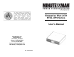
Enterprise Plus LCD RTXL UPS Series User's Manual Para Systems, Inc. 1455 Lemay Dr. Carrollton, TX 75007 Phone: 1-972-446-7363 Fax: 1-972-446-9011 Internet: minutemanups.com UPS Sizing: sizemyups.
1. Introduction 2 2. Controls and Indicators 6 3. Installation 9 4. Operation 15 5. Troubleshooting 19 6. Replacing the Battery 20 7. Obtaining Service 23 8. Specifications 24 9. Configurable Parameters & Settings 26 10. Limited Product Warranty 27 A1.
This symbol indicates "Equipment Grounding Conductor" Thank you for purchasing this power protection product. It has been designed and manufactured to provide many years of trouble free service.
CAUTION! This UPS series is ONLY intended to be installed in an indoor temperature controlled environment that is free of conductive contaminants. This UPS series is not intended for use in a computer room as defined in the Standard for the Protection of Electronic Computer/Data Processing Equipment ANSI/NFPA 75. CAUTION! The Maximum ambient operating temperature for this UPS series is 40°C (“0 ~ 40°C” for Ambient Operation).
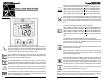
The Load Level Bar Graph operates as follows: LED #1: When the attached load is >20% the LED will illuminate. LED #2: When the attached load is >40% the LED will illuminate. LED #3: When the attached load is >60% the LED will illuminate. LED #4: When the attached load is >80% the LED will illuminate. LED #5: When the attached load is >100% the LED will illuminate.
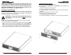
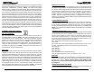
REAR PANEL INSTALLATION PLACEMENT 1. The RS232 Communications Port is for UPS monitoring and control. 2. The USB Communications Port is for UPS monitoring and control. (See Note on pg 17). 3. The RJ11 REPO (Remote Emergency Power Off) Port is for UPS control. This connection is not for Telecommunication use. 4. The option slot is for option cards. 5. The External Battery Connector is for connecting External Battery Packs. 6. The Battery Backup output receptacles.
NOTE: If you are using an External Battery Pack with this UPS series, the UPS must be configured so that the UPS will report the correct estimated runtime on the LCD screen and in the Power Monitoring software and/or the SNMP card. See the Power Monitoring software or the SNMP card’s User's Manual to configure the UPS. RACKMOUNT CONFIGURATION This UPS comes with mounting brackets for the standard 19" (46.5cm) rack installed on the UPS. The mounting brackets to fit a 23" (59.
TOWER CONFIGURATION The tower configuration allows the user to install the UPS in the up-right position next to a tower computer. The tower brackets are provided with the UPS. WARNING: Use two or more people when installing the UPS. Use CAUTION, the UPS is extremely heavy. 1. Once the location of the UPS has been determined, place the tower brackets in the desired location. WARNING: The UPS must be installed in the proper up-right position.
CONNECTING YOUR EQUIPMENT Plug the equipment into the output receptacles on the rear panel of the UPS. Do not use extension cords, adapter plugs or surge strips on the output of the UPS. Ensure that you do not exceed the maximum output rating of the UPS (refer to the information label or the Electrical Specifications in this manual). CAUTION! DO NOT connect a laser printer to the output receptacles on the UPS, unless the UPS is rated 2000VA or greater.
The UPS will charge the batteries with the UPS in the on or off position as long as the UPS is plugged into the wall outlet and there is an acceptable AC voltage present (80 - 164VAC/150 - 271VAC). NOTE: The input circuit breaker MUST be in the on position for the 208V models.
OPTION SLOT The option slot on the rear panel of the UPS is for option cards. Contact your local dealer for the available option cards. RJ11 REPO (Remote Emergency Power Off) PORT Connect one end of the RJ11 cable to the REPO port and the other end of the RJ11 cable to the EPO switch. In the AC or the Battery mode short pin4 to pin5 for approximately 0.5-seconds to shutdown the UPS. The UPS must be turned off and then back on again to restart the UPS. The LCD will display EPo for this function.
CAUTION: Replace batteries with the same number and type as originally installed in the UPS. These batteries have pressure operated vents. These UPSs contain sealed non-spillable maintenance-free lead acid batteries. REPLACING THE BATTERY (QUALIFIED SERVICE PERSONNEL ONLY) This UPS has an easy to replace hot-swappable batteries. Please read all of the WARNINGS and CAUTIONS before attempting to service the batteries. Typical battery life is 3 to 5 years. Environmental factors do affect battery life.
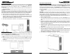
18. The UPS is now ready for the normal operation. 19. Properly dispose of the old battery module at an appropriate recycling facility or return them to the supplier in the packing material that the new battery module came in. NOTE: If the UPS has a Weak/Bad Battery Alarm after replacing the battery module, the user must initiate a self test to clear the Weak/Bad Battery Alarm. To initiate a self test see section 4 "SELF TEST". IF THE UPS REQUIRES SERVICE FIG. 1 FIG. 2 FIG. 3 FIG. 4 1.
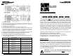
BATTERY SYSTEM Battery Type Sealed, Non-Spillable, Maintenance Free, Value Regulated Lead Acid Typical Recharge Time 8-hours to 90% after full load discharge Typical Battery Life SYSTEM SPECIFICATIONS Model Number E750RTXL2U E1000RTXL2U E1500RTXL2U 750VA 600W Maximum Power Capacity 1000VA 800W 1500VA 1200W 2000VA 1760W Number of Phase Single (1∅ 2W +G) Nominal Voltage 120VAC (208VAC) 3000VA 2560W 0 - 165VAC (0 - 300VAC) 80 - 164VAC (150 - 271VAC) Voltage Range Frequency Limits 50 or 60 H
(These items may require optional software or hardware) Factory Default UPS ID Enterprise Plus Series Function Battery install date Battery life in days User Choices Up to 64 charac- Use this function to uniquely ters to define the identify the UPS in your network configuration UPS Date of Date of battery manufacture replacement month/day/year XX/XX/XXXX Up to 5 1826 characters Enable/ Disable auto restart Enabled Set audible alarm state Enabled Shutdown Type Entire UPS Description Enable or Di
A1. DECLARATION OF CONFORMITY Notes: Application of Council Directive(s): 2004/108/EC Standard(s) to which Conformity is declared: EN61000-3-2, EN61000-3-3,EN62040-2, IEC61000-2-2 IEC61000-4-2, IEC61000-4-3, IEC61000-4-4, IEC61000-4-5, IEC61000-4-6, IEC61000-4-8, IEEE C62.41 Category A1 Manufacturer’s Name: Para Systems, Inc.