
User Manual


17
16
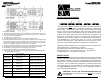
COMMUNICATIONS PORTS (RS232 and USB)
The RS232 communication port is a standard DB9 female with both RS232
and simulated contact closure capability. The UPS will poll the port and acti-
vate the port for RS232 or contact closure in accordance with the type of
cable it finds connected to the port. To change the port configuration requires
the unit be turned off and restarted with the desired cable connected. The
pinout for the port is depicted per the chart below:
Pin 1: Simulated contact closure Low Battery Warning, NO
Pin 2: /TXD
Pin 3: /RXD and receive UPS shutdown command (connect to pin 9 for 4-
seconds. The shutdown command is only active in the battery mode)
Pin 4: Not Used
Pin 5: Ground
Pin 6: Not Used
Pin 7: Not Used
Pin 8: Simulated contact closure AC fail, NO
Pin 9: Atx Signal (high level: +12V +/-2V, low level: -15V +/- -2V)
DIPSWITCH SETTINGS
The dipswitch setting may be changed by the user to set the desired Inverter
(On-Battery) output voltage. The dipswitch must be set to the desired Inverter
(On-Battery) output voltage and then the UPS must be turned off and restarted
to reconfigure the microprocessor and save the changes. The Inverter (On-
Battery) output voltage setting can be either 120VAC (208VAC) default or
125VAC (240VAC). Changing the Inverter (On-Battery) output voltage to
125VAC, will also change the Buck setpoint. Changing the Inverter (On-
Battery) output voltage to 240VAC, will also change the Brownout, Boost, Buck
and Overvoltage setpoints.
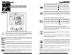
SELF TEST
The self test feature is useful to verify the correct operation of the UPS and the
condition of the batteries. With the UPS in the AC normal mode, press and
hold the On/Off/Test Button for four beeps, then release the button. The UPS
will perform a ten-second self test. During the self test, the UPS will switch to
the battery mode and the On-Battery icon will illuminate and the audible alarm
will sound. The length of the test that is automatically performed every two
weeks is longer than the start-up or user invoked test. This test will run for
approximately fifteen-seconds to measure the battery’s capability to provide
an acceptable amount of runtime. If the UPS fails a self test, one of the icons
will remain illuminated indicating the type of problem. NOTE: The UPS will
automatically perform a self test on start-up and every two weeks.
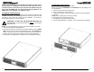
LOAD SHEDDING FUNCTION
The output receptacles are electrically wired into two segments to support the
"Load Shedding Function" (Labeled Load 1 & Load 2). The user can control
the two segments individually or both at the same time. The Load Shedding
Function is controllable by the Power Monitoring Software or the SNMP card.
NOTE: The output segment labeled Load 3 does not support the "Load Shed-
ding Function".
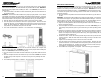
TURNING THE UNIT ON/OFF
On / Off / Test Button
Press and release the On/Off/Test Button after one beep to turn the UPS on
and supply power to the load. NOTE: The input circuit breaker (on the rear
panel) MUST be on for the 208V models. The load is immediately powered
while the UPS runs a five-second self test. Press and release the On/Off/Test
Button after one beep to turn the UPS off. NOTE: Turn the input circuit
breaker (on the rear panel) off for the 208V models. The UPS will continue to
charge the batteries whenever it is plugged into a wall outlet and there is
acceptable AC voltage present. NOTE: The input circuit breaker (on the rear
panel) MUST be on for the 208V models.
The UPS will charge the batteries with the UPS in the on or off position as long
as the UPS is plugged into the wall outlet and there is an acceptable AC voltage
present (80 - 164VAC/150 - 271VAC). NOTE: The input circuit breaker
MUST be in the on position for the 208V models. When a blackout, brownout,
or an overvoltage condition occurs; the UPS will transfer to the battery mode,
the On-Battery icon will illuminate and the audible alarm will sound once every
ten-seconds indicating that the commercial power is lost or unacceptable.
When the commercial power returns or is at an acceptable level, the UPS will
automatically transfer back to the AC normal mode and start recharging the
batteries. During an extended outage when there is approximately two-min-
utes of backup time remaining the audible alarm will sound twice every five-
seconds. This Low Battery Warning is letting the user know that they should
save all open files and turn off their computer. When the batteries reach the
predetermined level the UPS will automatically shutdown protecting the batter-
ies from over discharging. Once the commercial power returns the UPS will
automatically restart, providing safe usable power to the connected equipment
and start recharging the batteries.
POWER MONITORING SOFTWARE
The UPS comes with a Power Monitoring Software CD. See the software CD
for the installation of the Power Monitoring Software.
USB PORT
The USB protocol is HID. The HID USB driver is standard in the Windows OS.
Simply plug the USB cable into the UPS and the computer then follow the
prompts on the screen. NOTE: When using the UPS's USB port with
Windows XP, 7 or 8 the Power Options in the Control Panel may need to
be configured.