
User Manual


9
8
INSTALLATION PLACEMENT
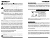
This UPS series is ONLY intended to be installed in an indoor temperature
controlled environment that is free of conductive contaminants. DO NOT oper-
ate the UPS in: extremely dusty and/or unclean areas, locations near heating
devices, water or excessive humidity, or where the UPS is exposed to direct
sunlight. Select a location, which will provide good air circulation for the UPS at
all times.
Route power cords so they cannot be walked on or damaged. This
UPS series is not intended for use in a computer room as defined in the
Standard for the Protection of Electronic Computer/Data Processing Equip-
ment ANSI/NFPA 75. Typical battery life is 3 to 5 years. Environmental
factors do affect battery life. High temperatures, poor utility power, and fre-
quent, short duration discharges have a negative impact on battery life.
Operating Temperature (Maximum): 0 to 40 degrees C (+32 to +104 degrees F)
Operating Elevation: 0 to 3,000m (0 to +10,000 ft)
Operating and Storage Relative Humidity: 95%, non-condensing
Storage Temperature: -15 to +45 degrees C (+5 to +113 degrees F)
Storage Elevation: 0 to 15,000m (0 to +50,000 ft)
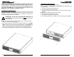
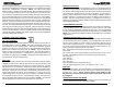
REAR PANEL
1. The RS232 Communications Port is for UPS monitoring and control.
2. The USB Communications Port is for UPS monitoring and control. (See Note on pg 17).
3. The RJ11 REPO (Remote Emergency Power Off) Port is for UPS control. This connec-
tion is not for Telecommunication use.
4. The option slot is for option cards.
5. The External Battery Connector is for connecting External Battery Packs.
6. The Battery Backup output receptacles. The output receptacles are electrically wired into
two segments to support the "Load Shedding Function" (Labeled Load 1 & Load 2). The
locking and Always On receptacles (Labeled Load 3) do not support the "Load Shed-
ding Function". NOTE: The locking recptacle is not on all models.
7. The input circuit breaker will trip in the event the load exceeds the UPS’s power rating.
8. The input power cord (120V models). The AC Power Inlet IEC320 (208V models).
9. The dipswitch is for setting the Inverter (On-Battery) output voltage.
10. The External Ground Stud is for connecting an external ground wire.
11. The R-J11/R-J45 modular connectors are used for 10/100 Base-T Network/single line
Phone/Fax/Modem protection.
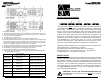
Output Power Receptacles
E750RTXL2U
NEMA 5-15P
Model #
E1500RTXL2U
E2000RTXL2U
E1000RTXL2U
E3000RTXL2U
E1500RTXLT2U
E3000RTXLT2U
NEMA 5-15P
NEMA 5-15P
NEMA 5-20P
NEMA L5-30P
NEMA L6-30P
NEMA 6-15P
6-NEMA 5-15R (Controllable)
2-NEMA 5-15R (Always On)
6-NEMA 5-15R (Controllable)
2-NEMA 5-15R (Always On)
6-NEMA 5-15R (Controllable)
2-NEMA 5-15R (Always On)
6-NEMA 6-15R (Controllable)
8-NEMA 5-15/20R (Controllable)
1-NEMA L5-20R (Always On)
7-NEMA 5-15/20R (Controllable)
1-NEMA L5-30R (Always On)
6-NEMA 6-15/20R (Controllable)
1-NEMA L6-30R (Always On)
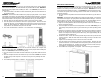
INSTALLATION
Be sure to read the installation placement and all the cautions before installing
the UPS. Place the UPS in the final desired location and complete the rest of
the installation procedure. These UPSs are shipped with the internal batteries
disconnected. The batteries must be connected before putting these UPSs
into service. See the "Rackmount Configuration" to install the UPS into the
rack and see the "Connecting the Batteries" procedure to connect the batter-
ies. USE CAUTION: The UPS is heavy. Use the appropriate number of
personnel when installing the UPS.
Input Power Plug
(All power cords are 10ft)
CAUTION! DO NOT USE THE MOUNTING BRACKETS TO
LIFT THE UPS. The mounting brackets are ONLY for securing the
UPS to the rack.