
User Manual


15
14
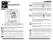
SYSTEM OVERVIEW
This Line-Interactive UPS protects computers, internetworking, and telecom-
munications equipment from blackouts, brownouts, overvoltages, and surges.
The AVR function continuously corrects the voltages, in-between the brownout
and overvoltage transfer points (80 - 164VAC/150 - 271VAC), to a safe usable
level. When the UPS is operating in the AVR mode the audible alarm will
remain silent and the AC Normal icon will flash. During normal AC operation,
the UPS will quietly and confidently protect your system from power anoma-
lies.
CHARGING THE BATTERY
The UPS will charge the internal batteries whenever the UPS is connected to
an AC source and there is an acceptable AC voltage present. NOTE: The
input circuit breaker MUST be in the on position for the 208V models. It is
recommended that the UPS's batteries be charged for a minimum of 4 hours
before use. The UPS may be used immediately, however, the “On-Battery”
runtime may be less than normally expected. NOTE: If the UPS is going to be
out of service or stored for a prolonged period of time, the batteries must be
recharged for at least twenty-four hours every ninety days.
CHECKING THE SITE WIRING FAULT (120V Models)
After plugging the UPS into the AC wall outlet, check the Site Wiring Fault
(SWF) icon on the front panel of the UPS. If the SWF icon is illuminated, the
UPS is plugged into an improperly wired AC wall outlet. If the UPS indicates a
Site Wiring Fault (SWF), have a Qualified Electrician correct the problem.
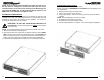
CONNECTING THE UPS TO AN AC SOURCE
Plug the UPS into a two pole, three wire, grounded AC wall outlet. The AC wall
outlet shall be near the UPS and shall be easily accessible. The plug on the
input power cord on this UPS series is intended to serve as a disconnect
device. Do not use extension cords, adapter plugs, or surge strips.
NETWORK/PHONE/FAX/MODEM PROTECTION CONNECTION (OP-
TIONAL)
Connect a 10/100 Base-T network, single line phone, Fax or Modem line to the
RJ11/45 modular connectors on the rear panel of the UPS. This connection
will require another length of telephone or network cable. The cable coming
from the telephone service or networked system is connected to the port marked
“IN”. The equipment to be protected is connected to the port marked "OUT".
NOTE: Connecting to the Network/Phone/Fax/Modem modular connectors is
optional. The UPS works properly without this connection.
CONNECTING YOUR EQUIPMENT
Plug the equipment into the output receptacles on the rear panel of the UPS.
Do not use extension cords, adapter plugs or surge strips on the output of the
UPS. Ensure that you do not exceed the maximum output rating of the UPS
(refer to the information label or the Electrical Specifications in this manual).
CAUTION!
DO NOT connect a laser printer to the output receptacles on
the UPS, unless the UPS is rated 2000VA or greater. A laser
printer draws significantly more power when printing than at
idle and may overload the UPS.
COMMUNICATIONS PORT CONNECTION (OPTIONAL)
The Power Monitoring Software and interface cables can be used with the
UPS. Use only the interface cables that come with these UPSs. Connect the
interface cable (Serial or USB) to the appropriate communications port on the
rear panel of the UPS. Connect the other end of the cable to the device that
will be monitoring/controlling the UPS. NOTE: Connecting to the Communi-
cations Port is optional. The UPS works properly without this connection. (For
USB port see Note on page 17).
RJ11 REPO (Remote Emergency Power Off) PORT (OPTIONAL)
Connect one end of the RJ11 cable to the REPO port and the other end of the
RJ11 cable to the EPO switch. In the AC or the Battery mode short pin4 to
pin5 for approximately 0.5-seconds to shutdown the UPS. The UPS must be
turned off and then back on again to restart the UPS. NOTE: Connecting to
the REPO port is optional. The UPS works properly without this connection.
This connection is not for Telecommnication use.
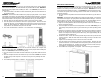
Block Diagram of the Basic Wiring and Internal Circuit Configuration