
User Manual


15
14
TURNING OFF THE STEP DOWN TRANSFORMER IN THE NORMAL AC
MODE:
1. Press and release the On/Off/Test Button on the front panel of the UPS aft-
er the second beep to transfer the UPS to the Bypass mode.
2. Turn off all of the connected equipment.
3. Turn off all of the Load breakers on the rear panel of the ED-XFR.
4. Turn off the input breaker on the rear panel of the UPS.
5. Turn off the DC breaker(s) on the rear panel of the Battery Pack(s).
TURNING OFF THE STEP DOWN TRANSFORMER IN THE BATTERY
MODE:
1. Turn off all of the connected equipment.
2. Turn off all of the Load breakers on the rear panel of the ED-XFR.
3. Press and release the On/Off/Test Button after the second beep to turn the
UPS off.
4. Turn off the input breaker on the rear panel of the UPS.
5. Turn off the DC breaker(s) on the rear panel of the Battery Pack(s).
START-UP IN THE BATTERY MODE:
The Battery Pack(s) must be connected to the UPS and the DC breaker(s) on
the rear panel of the Battery Pack(s) must be in the on position. The input of
the ED-XFR must be connected to the output of the UPS. The equipment must
be plugged into the output receptacles on the ED-XFR.
1. Turn on the input breaker on the rear panel of the UPS.
2. Press and release the On/Off/Test Button after the first beep to turn the
UPS on.
3. The fans will turn on, then the UPS will start-up and perform a self-diagno-
sis for approximately 10-seconds.
4. Turn on all of the Load breakers on the rear panel of the ED-XFR.
5. Turn on the connected equipment one at a time. See the UPS user's ma-
nual for more information.
1. Turn on the input breaker on the rear panel of the UPS. The fans will turn
on, the AC normal icon will flash off/on and the LCD will display ‘bPS’. The
UPS is now in the Bypass mode. NOTE: If there is a power interruption
while the UPS is in the Bypass mode the load will not be backed up.
2. Turn on all of the Load breakers on the rear panel of the ED-XFR.
3. Turn on the connected equipment one at a time.
4. Press and release the On/Off/Test Button after the first beep to turn the
UPS on.
5. The UPS will start-up and perform a self-diagnosis for approximately 10-
seconds. The UPS system is ready for normal opeartion. See the UPS
user's manual for more information.
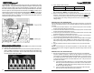
120V outputs:
La - N: 50A max, Lb - N: 50A max, the combined total for both: 83.4A max
208V output: Lc - Ld: 48.1A max
240V output: La - Lb: 41.7A max
NOTE: Default voltages for the output receptacles are 120V and 208V. 240V is
available, but only as a hardwire option at the output terminal block.
Chapter 4: Operation
START-UP IN THE NORMAL AC MODE:
The UPS must be connected to utility power and there must be an acceptable AC
voltage present. The Battery Pack(s) must be connected to the UPS and the DC
breaker(s) on the rear panel of the Battery Pack(s) must be in the on position. The
input of the ED-XFR must be connected to the output of the UPS. The equipment is
plugged into the output receptacles on the ED-XFR.
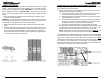
c) Connect the green wire labeled G on the input power cable to the ED-
XFR AC input terminal block ground terminal and secure.
2. Connect the other end of the #6 AWG input power cable labeled "TO UPS" to
the output terminal block on the UPS and secure.
a) Connect the black wire labeled L on the input power cable to the UPS out-
put terminal block labeled L and secure.
b) Connect the white wire labeled N on the input power cable to the UPS out-
put terminal block labeled N and secure.
c) Connect the green wire labeled G on the input power cable to the UPS out-
put terminal block ground terminal and secure.
3. Re-install the terminal block cover plate on the ED-XFR.
4. Before re-installing the terminal block cover box on the UPS, see the UPS us-
ers manual for the UPS input and output connections.
5. Plug the equipment into the output receptacles on the rear panel of the ED-
XFR. The ED8000RT-XFR and ED10000RT-XFR have a terminal block for ha-
rdwiring the output. Refer to the figure below for the input / output connections.
The pins for the output cable are included.
NOTE: The two 120V outputs are individual 5KVA outputs and they CANNOT be
paralleled.
Input / Output terminal block for the ED8000RT-XFR and ED10000RT-XFR: