ED6200RM Parallel Redundant ON-LINE SERIES User’s Manual Para Systems, Inc. 1455 LeMay Drive Carrollton, TX 75007 Phone: 1-972-446-7363 Fax: 1-972-446-9011 Internet: minutemanups.com UPS Sizing: sizemyups.
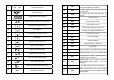
Table of Contents 1 Important Safety Instructions................................................... 2 1.1 An Important Notice............................................................... 2 1.2 Life Support Policy ................................................................ 3 1.3 FCC Notice............................................................................ 3 2 Product Introduction ................................................................. 4 2.1 System Overview..........................
1 Important Safety Instruction 1.1. An Important Notice 1.1.1 To ensure safety in all applications where a UPS system is hardwired to the electrical supply the UPS must be installed by a Qualified Electrical Contractor. 1.1.2 The UPS has its own internal energy source (battery). If the UPS is switched on when there is no AC power is available, there could be voltage at the output terminals. 1.1.3 Servicing of the UPS system must be performed by Qualified Service Personnel ONLY.
2 Product Introduction 2.2.8 This UPS system has the Independent Battery Bypass function. The Independent Battery Bypass function allows the UPS system to provide a stable, regulated, transient-free pure sine wave AC output power even when the batteries are weak or dead. 2.2.9 The battery management circuit analyses the battery discharging status to adjust the battery cut-off point and extend the life of batteries. 2.1.
11 LINE OFF UPS Abnormal Lock 12 27 Er01 DC BUS capacitor pre-charge abnormal after 50-seconds or Battery Fuse failure 28 Er02 AC SCR or Battery SCR soft Start abnormal after 2-seconds 29 Er03 PFC (Boost) soft start abnormal after 30seconds 30 Er04 Inverter Failure 31 Er05 Battery Weak or Dead 32 Er06 Output Short Circuit 33 Er08 DC Bus high-voltage-level abnormal 34 Er09 DC Bus low-voltage-level abnormal UPS Flow Chart 13 4 Digits Measurement Display 14 Indicate the item desi
2.4. Controls and Indicators 46 Er22 Bypass SCR or Output Fuse Fails 47 Er23 Inverter Relay or SCR or Output Fuse Fails 48 Er24 49 Er26 PFC Over-current 50 Er27 The UPS must be operated in normal mode in parallel system 51 Er28 Bypass Overload Time out and cut off output.
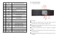
On/Alarm Silencer switch is to turn the UPS On or silence the audible alarm in 2.5.2 Isolation Transformer module (ED6000RMXFMR) rear panel the Battery mode. OFF switch is to turn the inverter Off and transfer the UPS to the Bypass mode. Special functions key: Log in/out. Down arrow: Go to next page. Up arrow: Go to previous page or change the UPS setting. Enter key: To save the changes to the UPS setting. 2.5. Rear Panels 2.5.1 UPS module (ED6200RM) rear panel A.
3.2. Installation Placement 3 Installation and Operation (QUALIFIED SERVICE PERSONNEL ONLY) Be sure to read the Installation Placement and all of the CAUTIONS and the WARNINGS before installing the UPS system. Place the UPS, the Isolation Transformer and the Battery Pack in the final desired location and complete the rest of the installation procedure. 3.1. Unpacking Remove the UPS, Isolation Transformer and Battery Pack from the packing boxes. USE CAUTION: This UPS system is extremely heavy.
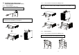
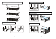
3.4.1.2 UPS, Isolation Transformer and Battery Pack 3.4. Installation of the Caster Covers (QUALIFIED SERVICE PERSONNEL ONLY) 3.4.1 Tower Installation 3.4.1.1 UPS and Battery Pack (only) Step1: Install the casters on the UPS; Isolation Transformer and Battery Pack, and then connect UPS, Isolation Transformer and Battery Pack together. Step1: Install the caster covers. S3 Step2: Install the casters on the UPS and Battery Pack, and then connect UPS, and the Battery Pack together. S3 S1 A3 3.4.
Step2 Install the rackmount brackets to the UPS, Isolation Transformer and Battery Pack S3 Step4 Install the Battery Pack to the Rails S3 Step5 Install the Rails in the 4-post Rack, and then install the Isolation Transformer to the Rails Step3 Install the Rails in the 4-post Rack Step6 Install the UPS in Rack 16 17
3.5. Wiring the Input and Output Connections (Qualified Electrical Contractor Only) 3.5.1 Connecting the Input and Output wires to the terminal block on the UPS module. The Utility Input MUST be Hardwired. CAUTION - To reduce the risk of fire, connect the UPS Utility input to a branch circuit with an over-current protection of 40 amperes in accordance with the National Electric Code, ANSI/NFPA 70. Use No. 8 AWG, 60°C copper wire and apply 22.1lb-in of torque force when connecting to the terminal blocks.
3.5.2.3.2 1. 2. 3. 4. 3.5.2.3.5 Configuration 1. Output: 208VAC 6KVA max load and two separate circuits of 120VAC 3KVA loads (3KVA max load per circuit). Total combined output load not to exceed 6KVA. Connect a jumper wire from L22 to N11. Circuit1: L22-Line, N22-Neutral, G-Earth Ground. Circuit2: L11-Line, N11-Neutral, G-Earth Ground. Circuit3: L12-L1, N22-L2, G-Earth Ground. Connect the Black wire labeled L12 to terminal L12. Connect the White jumper wire from N11 to terminal L22.
3.5.2.3.7 Configuration 3. Output: 240VAC 6KVA load and two separate circuits of 120VAC 3KVA loads (3KVA max load per circuit). Total combined output load not to exceed 6KVA. Connect a jumper wire from L22 to N11. Circuit1: L22-Line, N22-Neutral, G-Earth Ground. Circuit2: L11-Line, N11-Neutral, G-Earth Ground. Circuit3: L11-L1, N22-L2, G-Earth Ground. 3.5.2.3.9 Configuration 5. Output: Two separate circuits of 120VAC 3KVA loads (3KVA max load per circuit). Total combined output load not to exceed 6KVA.
3.5.2.3.11 Configuration 7. Output: 208VAC 6KVA load, 240VAC 6KVA load and two separate circuits of 120VAC 3KVA loads (3KVA max load per circuit). Total combined output load not to exceed 6KVA. Connect a jumper wire from L22 to N11. Circuit1: L22-Line, N22-Neutral, G-Earth Ground. Circuit2: L11-Line, N11-Neutral, G-Earth Ground. Circuit3: L12-L1, N22-L2, G-Earth Ground. Circuit4: L11-L1, N22-L2, G-Earth Ground. 120Vac 3.5.3.1 Application B: 1. Utility Input: 208/240VAC must be hardwired (see Section 3.5.
3.5.4 Hardwiring the Input and Output wires to the terminal block on the UPS module when using the UPS without the Isolation Transformer module. CAUTION - To reduce the risk of fire, connect the UPS Utility input to a branch circuit with an over-current protection of 40 amperes in accordance with the National Electric Code, ANSI/NFPA 70. Use No. 8 AWG, 60°C copper wire.
3.7. Operation and Setup Instructions 3.7.1 Startup in the Normal Mode 3.7.1.1 Switch the Utility power circuit breaker (at the service panel) to the On position. 3.7.1.2 Switch the UPS’s Input circuit breaker (on the rear panel) to the On position. 3.7.1.3 The UPS will startup. The Green LEDs & will illuminate to show the Utility and Bypass Inputs are normal. The LCD display will display drawing A then drawing B. 3.7.1.
3.7.1.7 The UPS has successfully passed the start-up procedure. The UPS will charge the batteries whenever the UPS is connected to an AC source and there is an acceptable AC voltage present. It is recommended that the UPS's batteries be charged for a minimum of 8-hours before use. However the UPS may be used immediately, but the “On-Battery” runtime maybe less than normally expected.
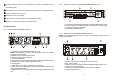
P K * It shows the input frequency from the Bypass Input. * It shows the Internal Temperature of the UPS System. 3.7.4 UPS Default Data and Special Function Features 3.7.4.1 Once the UPS has successfully started up, press the Special Function keypad to change the LCD display screen to drawing Q1. L * It shows the Output Voltage from the Inverter. Q1 M * It shows the Buzzer is “Enabled”. * It shows the Output Frequency from the Inverter. Q2 N * It shows the Buzzer is “Disabled”.
R1 U * It shows the Self-test is “Disabled”. * It shows the Inverter Output Voltage setting. V1 R2 * It shows the UPS is operated in the “Normal mode”. * It shows the Self-test is “Enabled”. V2 S1 * It shows the UPS is operated in the “Eco mode”. * It shows the Bypass Voltage is adjusted to the lower limit. V3 S2 * It shows the UPS is operated in the “CVCF 50Hz mode”. * It shows the bypass voltage is adjusted to the higher limit. V4 T * It shows the Frequency Window is +/-3Hz.
W *It shows the Fine Tune Adjustment % from 0% to 3% or -0% to -3%. X * It shows the UPS Identification Number. 3.7.5.3 Drawings S1 and S2 mean the bypass input window, can be changed to 184VAC~260VAC or 195VAC~260VAC. 3.7.5.4 Drawing T means the bypass frequency window of the Inverter Output can be changed to ±3Hz or ±1Hz. 3.7.5.5 Drawing U means the Inverter Output Voltage can be changed to 200VAC, 208VAC, 220VAC, 230VAC, or 240VAC. 3.7.5.
3.7.6 UPS Is Off Due to Unknown Reason 3.7.6.1 If a serious abnormal condition occurred, the UPS will lock it itself in the “OFF” position as shown in drawing AA and a error message will be displayed on the LCD screen. 3.7.6.2 After 3 seconds, all messages will be locked except the Bypass messages (LED & LCD ). If the utility voltage is abnormal after the UPS is locked, the LED will be extinguished and the LCD will be shown on the LCD screen. 3.7.6.
4.2. EPO (Emergency Power Off) Port Connect one end of a two-wire cable to the EPO port and the other end of the two-wire cable to an EPO switch, and then short pin1 to pin2 for approximately 1.0-second to shutdown the UPS in the AC or the Battery mode. The LCD display will display EPO and Line OFF every 6-seconds and the audible alarm will be continuous. The UPS must be turned off and then turned back on again to restart the UPS.
6 Troubleshooting Guide 7 Replacing the Batteries If the UPS malfunctions, check the followings: a. Is the wiring of the input and the output correct? b. Is the input voltage within the acceptable window of the UPS? If items a. and b. above are correct then proceed with the following chart. If the problem persists, see Obtaining Service. Situation UPS Red Fault LED lights up Check Items Solution Check the error code shown on the LCD screen 1.
7.1. Battery Replacement Procedure 7.1.11 Cut the cable ties from the battery trays. (QUALIFIED SERVICE PERSONNEL ONLY) This UPS system has Hot-swappable batteries. Hot-swappable batteries mean that the batteries can be replaced without powering down the whole UPS system. NOTE: If there is a power interruption while replacing the hot-swappable batteries, with the UPS system ON, the load will not be backed up. To hot-swap the batteries start with step number 7.1.6 and omit step number 7.1.7. 7.1.1 7.1.
7.1.14 7.1.15 7.1.16 7.1.17 7.1.18 7.1.19 Gently remove the top part of the plastic battery tray. Disconnect the red battery wire from the battery terminal. Disconnect the black battery wire from the battery terminal. Disconnect the 3-battery jumper wires from the battery terminals. Remove the 4-defective batteries from the battery tray and set aside. Install the 4-new batteries in the battery tray in the same position as the original batteries. 7.1.20 Observe polarity.
9 Obtaining Service BATTERY (The batteries are in the Battery Pack ONLY. The UPS module does NOT have internal batteries.) Type Typical Recharge Time Typical Battery Life System Voltage Quantity/Rating Battery part numbers Runtime (full/half load) Sealed, Non-Spillable, Maintenance Free, Valve Regulated, Lead Acid 8-hours from total discharge 3 - 5 years, depending on the number of charge and discharge cycles, and ambient temperature 240VDC 20-12V7.
10 Limited Product Warranty Para Systems, Inc. (Para Systems) warrants this equipment, when properly applied and operated within specified conditions, against faulty materials or workmanship for a period of three years from the date of purchase. For equipment sites within the United States and Canada, this warranty covers repair or replacement of defective equipment at the discretion of Para Systems. Repair will be from the nearest authorized service center.