
User`s manual


46
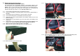
7.1.14 Gently remove the top part of the plastic battery tray.
7.1.15 Disconnect the red battery wire from the battery terminal.
7.1.16 Disconnect the black battery wire from the battery terminal.
7.1.17 Disconnect the 3-battery jumper wires from the battery terminals.
7.1.18 Remove the 4-defective batteries from the battery tray and set aside.
7.1.19 Install the 4-new batteries in the battery tray in the same position as the
original batteries.
7.1.20 Observe polarity. Reconnect the 3-battery jumper wires to the battery
terminals.
7.1.21 Observe polarity. Reconnect the black battery wire to the battery terminal.
7.1.22 Observe polarity. Reconnect the red battery wire to the battery terminal.
7.1.23 Reinstall the top part of the plastic battery tray on top of the batteries.
NOTE: Make sure that all of the battery wires remain on top of the batteries and
inside the plastic battery tray.
7.1.24 Reinstall the battery tray in the Battery Pack module. USE CAUTION: The
battery trays are extremely heavy.
NOTE: DO NOT pinch the battery wires between the batteries and the Battery Pack
chassis.
7.1.25 Reconnect the red and black Anderson battery connectors.
7.1.26 Install new cable ties through the holes in the battery tray then around the
battery wires (see 7.1.11).
7.1.27 Once all the battery trays are complete reinstall the front panel.
7.1.28 Reinstall the front panel retaining screws.
7.1.29 Reconnect all of the communications and network cables (if applicable).
7.1.30 Reconnect the battery cables (if applicable).
7.1.31 Turn On the DC circuit breaker (s) on the rear panel of the Battery Pack
module (s).
7.1.32 Turn On the utility power circuit breaker at the service panel (if applicable).
7.1.33 Turn On the input circuit breaker on the rear panel of the UPS (if applicable).
7.1.34 Press and hold the On Switch (on the front panel) for approximately 3-
seconds, then release (if applicable).
7.1.35 Turn On the equipment that is connected to the UPS (if applicable).
7.1.36 The UPS system is now ready for the normal operation.
7.1.37 Properly dispose of the old batteries at an appropriate recycling facility or
return them to the supplier in the packing material for the new batteries.
47
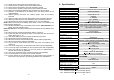
8 Specifications
MODEL
ED6200RM
Topology Double Conversion On-Line, True Sine Wave
Maximum Power Capacity 6000VA/4200Watts
INPUT
Number of Phases Single (1Ø 2W +G)
Nominal Voltage 208VAC
Acceptable Input Voltage 0 - 300VAC
Voltage Range 160* - 280VAC
Power Factor Correction >98% at Full Load
Frequency Limits 50/60Hz +/-5Hz autosensing
Low Voltage Transfer Point 160V resets to utility power at 175V or higher
High Voltage Transfer Point 280V resets to utility power at 265V or lower
Protection Re-settable Circuit Breaker
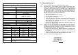
OUTPUT
Waveform Type True Sine Wave
Nominal Voltage with Isolation
Transformer
120VAC and 208/240VAC
Nominal Voltage without
Isolation Transformer
208/240VAC
Voltage Regulation +/-2% (until Low Battery Warning)
Frequency 50/60Hz +/-0.2Hz (unless synchronized to utility)
Voltage T.H.D. <3% (Linear load)
Dynamic Response +/-5% @ 100% Load change in 100ms
Transfer Time 0ms
Slew Rate <1Hz / second
Efficiency (Line Mode) >87% (Full Load)
Crest Factor 3 : 1
Overload Capacity >105% - <155% for 160 seconds
>156% shutdown immediately
Protection
Over-Current, Short-Circuit and Latching Shutdown
SURGE PROTECTION AND FILTERING
Surge Energy Rating 1050 J
Surge Energy Capability 6500 Amps total
Surge voltage let-through (as a
percentage of an applied ANSI
C62.41 Cat. A +/-6KV)
<5%
Noise Filter
Normal and common mode EMI/RFI suppression
Audible Noise at 1 m (3 ft.) <50dB
* 160 – 280VAC at loads <50% of the rated capacity
* 175 – 280VAC at loads <75% of the rated capacity
* 180 – 280VAC at loads >75% of the rated capacity