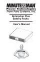
Enterprise Plus Battery Packs User's Manual
English 1. Introduction 2 2. Controls and Indicators 6 3. Installation 7 4. Operation 14 5. Troubleshooting 15 6. Replacing the Battery 16 7. Obtaining Service 20 8. Specifications 21 9.
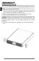
English Thank you for purchasing this power protection product. It has been designed and manufactured to provide many years of trouble free service.
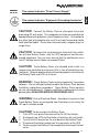
This symbol indicates "Equipment Grounding Conductor" CAUTION! Connect the Battery Pack to a two pole, three wire grounding AC wall outlet. The receptacle must be connected to the appropriate branch protection (circuit breaker or fuse). Connection to any other type of receptacle may result in a shock hazard and violate local electrical codes. Do not use extension cords, adapter plugs, or surge strips.
WARNING: Qualified Service Personnel ONLY must perform English the Installation and Servicing of these Battery Packs. MINUTEMAN accepts no liabilities and is not limited to: injury to the Service Personnel, or damages to; the Battery Pack, the UPS, or the connected equipment caused by the incorrect installation or servicing of the Battery Packs.
After removing your Battery Pack from its carton, it should be inspected for damage that may have occurred in shipping. Immediately notify the carrier and place of purchase if any damage is found. Warranty claims for damage caused by the carrier will not be honored. The packing materials that your Battery Pack was shipped in are carefully designed to minimize any shipping damage. In the unlikely case that the Battery Pack needs to be returned to the manufacturer, please use the original packing material.
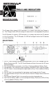
English INDICATOR PANEL The Charger Active (green) LED illuminates in a steady state when the Charger is on. The Charger Active LED will extinguish when there is no acceptable AC present. The DC Breaker On (green) LED illuminates in a steady state when the DC breaker is in the On position. The DC Breaker On LED will extinguish when the DC breaker is in the Off position. REAR PANEL 1. The DC Circuit Breaker connects and disconnects the DC bus voltage from the Battery Pack to the UPS.
English INSTALLATION PLACEMENT These Battery Packs are intended to be install in a temperature controlled environment that is free of conductive contaminants. Select a location which will provide good air circulation for the Battery Pack at all times. Avoid locations near heating devices, water or excessive humidity, or where the Battery Pack is exposed to direct sunlight. Route power cords so they cannot be walked on or damaged.
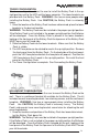
English RACKMOUNT CONFIGURATION The Battery Pack comes with mounting brackets for the standard 19" (46.5cm) rack. The mounting brackets to fit a 23" (59.2cm) standard rack are also available. The screws for mounting the Battery Pack to the rack are not included (screw size varies with rack size). 1. Locate the mounting bracket screw holes on the side panels of the Battery Pack, at the front of the Battery Pack. NOTE: The mounting brackets can also be mounted in the middle of the Battery Pack. 2.
WALLMOUNT CONFIGURATION The wallmount configuration allows the user to mount the Battery Pack on the wall. There is a wallmount bracket kit available for the Battery Pack. The kit includes two wall mounting brackets, ten retaining screws, and the wallmount template. WARNING: Use two or more people when installing the Battery Pack. Use CAUTION, the Battery Pack is extremely heavy. The Battery Pack's side panels have mounting bracket screw holes for attaching the wall mounting brackets. 1.
English WALLMOUNT CONFIGURATION (continued) 2. Align the mounting brackets with the mounting bracket screw holes and attach with the six retaining screws. 3. Use the template to mark the screw hole position on the wall. CAUTION, you should always were protective gear for your hands and eyes when operating power tools. 4. Attach the four retaining screws to the wall and make sure that all of the retaining screws are screwed into structural material. Then clean the area of any loose material.
NOTE: The EBP72XL's External Battery Cable has a strain relief that must be attached (with the screw) to the rear panel of the UPS. EBP72XL's External Battery Cable with strain relief.
English CONNECTING THE BATTERY PACK TO AN AC SOURCE These Battery Packs can operate with 115VAC or 230VAC input voltage. Before connecting the Battery Pack to an AC Source, verify that the Battery Pack's dipswitch is set for the proper input voltage. 1. Set the dipswitch on the rear panel of the Battery Pack to the appropriate input voltage. 2. Connect the input power cord for the Battery Pack into the AC Inlet on the Battery Pack. 3.
NOTE: The EBP72XL's External Battery Cable has a strain relief that must be attached (with the screw) to the rear panel of the UPS. EBP72XL's External Battery Cable with strain relief. 13 English 7. Before connecting the Battery Pack to an AC Source, verify that the Battery Pack is set for the proper input voltage. Set the dipswitch on the rear panel of the Battery Pack to the appropriate input voltage. Connect the input power cord with the NEMA 5-15P Plug into the AC Inlet on the first Battery Pack. 8.
English English SYSTEM OVERVIEW These Battery Packs will extend the runtime capabilities of the UPS. These Battery Packs have internal chargers to properly maintain the internal batteries. The charger will operate with 115VAC or 230VAC depending on the dipswitch setting. The Battery Pack will charge the batteries with the DC circuit breaker in the On or Off position as long as the Battery Pack is plugged into the AC wall outlet and there is an acceptable AC voltage present (90 - 130VAC/180 - 260VAC).
English Symptom Possible Cause What To Do The Charger Active 1. The input power cord is 1. Plug the input power cord not plugged into the AC wall into the AC wall outlet. LED is not on. outlet. 2. Once commercial power is 2. No commercial power available recheck the LED. available. 3. Check the circuit breaker 3. No AC voltage at the AC at the service panel to see if it is tripped. wall outlet. 4. Internal charger fault. 4. Call for Service. The DC Breaker On 1. The DC circuit breaker 1.
English REPLACING THE BATTERY (QUALIFIED SERVICE PERSONNEL ONLY) These Battery Packs have an easy to replace hot-swappable batteries. Please read all of the WARNINGS and CAUTIONS before attempting to service the batteries. NOTE: If there is a power interruption while replacing the hot-swappable batteries, the the UPS on, the load will not be backed up. WARNING! This Battery Pack contains potentially hazardous voltages. Do not attempt to disassemble the Battery Pack beyond the battery replacement procedure.
Model # Battery Qty/Rating CSB Part # Panasonic Part # Yuasa Part # EBP36XL EBP72XL 6-12V7.2Ah 6-12V8.5Ah GP 1272 F2 HR 1234W F2 LC-R127.2 LC-R129 NP-7.2-12 REW45-12 BATTERY REPLACEMENT PROCEDURE (QUALIFIED SERVICE PERSONNEL ONLY) PLEASE READ THE CAUTIONS AND WARNINGS BEFORE ATTEMPTING TO REPLACE THE BATTERIES Hot-swappable batteries mean that the batteries can be replaced without powering down the whole UPS system.
English 15. Grasp the other battery pull tab and gently pull the battery module out of the Battery Pack and set on the floor. (FIG. 4) NOTE: Use Caution, the battery modules are heavy. 16. Disconnect the battery positive (red) wires. 17. Disconnect the battery negative (black) wires. 18. Disconnect the battery jumper wires. 19. Remove the old batteries from the battery tray. 20. Install the new batteries into the battery tray in the same position as the original batteries. 21. Verify proper polarity.
English FIG. 2 FIG. 3 FIG.
English IF THE UPS REQUIRES SERVICE 1. Use the TROUBLESHOOTING section to eliminate obvious causes. 2. Verify there are no circuit breakers tripped. A tripped circuit breaker is the most common problem. 3. Call your dealer for assistance. If you cannot reach your dealer, or if they cannot resolve the problem call or fax MINUTEMAN Technical Support at the following numbers; Voice phone (972) 446-7363, FAX line (972) 446-9011 or visit our Web site at www.minutemanups.com the "Discussion Board".
English SYSTEM SPECIFICATIONS Model Number Format EBP72XL EBP36XL Rack/Tower Convertible / Wallmount CHARGER INPUT Number of Phases Single (1∅ 2W +G) Nominal Voltage 115/230VAC (dipswitch selectable) Voltage Range 115VAC: 90 - 130VAC (230VAC: 180 - 260VAC) 2.6 Amps AC Current Frequency Limits Input Protection 50 or 60 Hz, +/-6Hz, autosensing Resettable Circuit Breaker CHARGER OUTPUT DC Voltage 41.4VDC +/-5% DC Current Output Protection 82.8VDC +/-5% 2.
English Para Systems Inc. (Para Systems) warrants this equipment, when properly applied and operated within specified conditions, against faulty materials or workmanship for a period of three years from the date of purchase. For equipment sites within the United States and Canada, this warranty covers repair or replacement of defective equipment at the discretion of Para Systems. Repair will be from the nearest authorized service center. Replacement parts and warranty labor will be borne by Para Systems.
LIMITED PRODUCT WARRANTY EXCEPT AS PROVIDED ABOVE, IN NO EVENT WILL PARA SYSTEMS BE LIABLE FOR DIRECT, INDIRECT, SPECIAL, INCIDENTAL, OR CONSEQUENTIAL DAMAGES ARISING OUT OF THE USE OF THIS PRODUCT, EVEN IF ADVISED OF THE POSSIBILITY OF SUCH DAMAGE. Specifically, Para Systems is not liable for any costs, such as lost profits or revenue, loss of equipment, loss of use of equipment, loss of software, loss of data, cost of substitutes, claims by third parties, or otherwise.
English Notes: 24
Para Systems, Inc. 1455 Lemay Dr. Carrollton, TX 75007 Phone: 1-972-446-7363 Fax: 1-972-446-9011 Internet: minutemanups.com UPS Sizing: sizemyups.