Kleen Sweep 35W Sweeper OPERATION SERVICE Model HM35BQP PARTS CARE
This manual is furnished with each new MINUTEMAN KLEEN SWEEP 35WTM. This provides the necessary operating and preventive maintenance instructions. Operators must read and understand this manual before operating or servicing this machine. This machine was designed to give you excellent performance and efficiency. For best results and minimal cost, please follow the general guidelines below: Operate the machine with reasonable care.
TABLE OF CONTENTS Operation, Illustration, Spare Parts, and Maintenance IMPORTANT SAFETY INSTRUCTIONS ............................................................. 5 INSPECTION ................................................................................................................ 6 KLEEN SWEEP 35W – HOW IT WORKS.......................................................................... 8 ASSEMBLY .......................................................................................................
IMPORTANT SAFETY INSTRUCTIONS Operators must read and understand this manual before operating or maintaining this machine. Do not operate this machine in flammable or explosive areas. The following information below may cause a potential hazard to the operator and equipment. Read this manual carefully and be aware when these conditions can exist. Take necessary steps to locate all safety devices on the machine and train the personnel operating the machine.
Avoid contact with battery acid. Battery acid can cause burns. When working on or around batteries, wear protective clothing and safety glasses. Remove metal jewelry. Do not lay tools or metal objects on top of batteries. Charging batteries generates explosive gasses. Do not charge batteries when open flames or sparks are present. Do not smoke. Make sure the charger is turned off before disconnecting it from the machine.
Special Instructions for Handling Batteries Never leave batteries in discharged condition for an extended period of time, but re-charge them as soon as possible. In order to preclude risks to health, eating, smoking and drinking are forbidden in battery charging stations and rooms. Satisfactory ventilation must exist in the battery charging area. Batteries must not be connected to or disconnected from the power supply as long as they are energized. Top up using distilled water only.
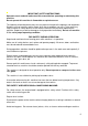
Kleen Sweep 35W – How it Works The side broom is going to collect dirt out of corners & niches and carries it into the track of the main broom. Fine dust involved is extracted by a suction fan and held back by a filter. Dustfree only air will exit the machine. First Operation Assembly To reduce the box volume the handlebar is folded forward and the side broom is packed unassembled. Assemble these items as follows: • Unfold the handlebar and secure on both sides with the enclosed hex nuts and washers.
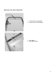
Operation of the Kleen Sweep 35W 1. Traction Drive control bow 2. Control lever for side broom 1 2 1. Key Switch 2.
1. Hand wheel for broom roller vertical adjustment 2. Pedal to set parking brake.
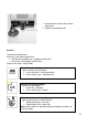
Key-switch Turn ignition ON/OFF, secures machine against unauthorized use 0 = OFF I = ON Hand wheel for Main Broom Adjustment Adjust roller brush load (sweeping track width). Best setting is 2” (50mm). • Turn Hand wheel CW = Reduced track width (low brush load) • Turn Hand wheel CCW = Extended track width (high brush load) Pilot light, GREEN Turns ON, when Key switch is ON Key-switch Connect and disconnect the drive motor and to secure the machine against unauthorized use.
Empty Dirt hopper 1 Dirt hopper control lever 3 Bar for dirt hopper wheels • • • 2 Latch 4 Dirt hopper Depress lever (1) to the right to unlock Hold dirt hopper by its handle (3) and pull to the rear, empty hopper Slide dirt hopper into opening, exert pressure against latch (2) until click is audible, to ensure the dirt hopper is installed in place. Traction Drive The traction drive system uses a friction wheel (1) and a V-belt (2) driving the wheel axle.
the other half. Pull drive pin out of broom shaft. For installation, reverse the above sequence of operations. Adjust Sweeping Track In case of broom roller wear and after replacing the roller broom, adjust sweeping pattern as follows: • Start the machine and rotate broom roller for a short period of time (static) • Lift front end of machine and pull back. • If adjusted properly, a parallel line of sweep is visible on the ground (sweeping track). This sweeping track width is adjusted to approx.
1 side broom attaching bolt 2 round belt for side broom drive 3 V-belt for broom roller drive Replacing the Side Broom V-Belt • Tilt the Kleen Sweep 35W back on its handlebar (refer to section, “Replace Broom Roller”) • Remove hood (3 ea. Screws) • Lift side broom and uncock round belt • Remove round belt and assemble new one. • NOTE: Refer to direction arrow.
1. Filter Module 2.
Maintenance Compliance with our recommended maintenance and service schedule will guarantee a dependable machine all the time. It is better and cheaper to take precautions instead of facing costly repair work. If your in-house facilities are unable to perform the work per maintenance schedule, your authorized distributor will be glad to conclude a maintenance agreement with you. For all inquiries or parts orders, always specify chassis and motor numbers as printed on the data plate.
Exploded views 17
Traction Drive Bild Item Rép. Best.-Nr. PN Réf. No. Stck. Qty. Oté. Teilbezeichnung Description 1 2 3 4 5 6 7 8 10-450 73-094 05-309 04-290 53-168 53-173 13-512 70-541 5 8 3 1 1 1 2 1 6kt-Schraube Sperrkantscheibe 6kt-Schraube Scheibe Riemenscheibe Bolzen Scheibe Kugellager Hex. bolt Detent washer Hex.
Traction Drive Bild Item Rép. Best.-Nr. PN Réf. No. 35 105-477 36 Stck. Qty. Oté. Teilbezeichnung Description 1 Batteriewanne Battery tray 107-555 1 Batteriestecker Connector 37 39 40 41 92-761 05-375 05-151 08-365 1 8 4 1 Schalter Scheibe 6kt-Mutter Gehäuse für Stecker Switch Washer Hex. nut Plug housing 42 08-364 9 Gehäuse für Hülse Socket housing 43 44 05-281 55-967 2 1 6kt.Mutter Flachsteckhülse Hex.
Travel Drive Bild Item Rép. Best.-Nr. PN Réf. No. 1 2 3 4 5 6 7 8 9 10 11 12 13 105-100 85-157 05-303 105-102 04-656 105-101 05-378 02-234 05-308 05-341 52-926 07-244 12-483 14 15 16 17 18 19 20 21 22 Stck. Qty. Oté. Teilbezeichnung Description 1 1 1 1 2 1 1 1 6 2 4 1 2 Hebel Gabelkopf 6kt-Schraube Bolzen DU-Buchse Halter Scheibe Sicherungsring 6kt-Schraube Federring Senkschraube Sicherungsring Kugellager Lever Fork head Hex. bolt Bolt DU-Bushing Holder Washer Retaining ring Hex.
Chassis – Covering Bild Item Rép. 1 2 3 4 5 6 7 8 9 10 11 12 13 14 15 16 17 18 19 20 21 22 23 24 25 26 27 28 29 30 31 32 33 34 35 36 37 38 39 40 41 42 43 44 Best.-Nr. PN Réf. No. Stck. Qty. Oté.
Chassis – Covering Bild Item Rép. Best.-Nr. PN Réf. No. 45 46 47 48 49 50 51 52 53 54 55 56 57 58 59 60 61 105-545 05-152 13-383 05-332 05-151 07-423 53-105 53-108 15-280 53-107 70-531 105-547 13-485 73-962 105-546 02-880 05-396 62 63 64 05-311 107-338 05-335 Stck. Qty. Oté.
Steering Handle Bild Item Rép. Best.-Nr. PN Réf. No. Stck. Qty. Oté. Teilbezeichnung Description 1 2 12-223 53-161 1 1 Kugelknopf Schalthebel Ball end Shift lever 3 4 5 6 7 05-152 15-120 07-790 07-244 105-265 1 1 1 2 1 6kt-Mutter Scheibe DU-Buchse Sicherungsring Lenkholm Hex. nut Washer DU-bushing Retaining ring Steering handle 8 9 10 11 105-264 05-302 107-084 53-165 1 1 1 1 Griffbügel 6kt-Schraube Bowdenzug Schaltwelle Bow, handle Hex.
Sweep Roller with Travel Drive Bild Item Rép. Best.-Nr. PN Réf. No. Stck. Qty. Oté. Teilbezeichnung Description 1 2 53-129 05-758 1 3 Riemenscheibe Spannhülse Belt pulley Tensioning sleeve 3 4 5 6 7 8 9 10 07-654 92-852 05-373 05-152 105-510 53-132 91-179 15-774 4 2 4 4 1 1 1 1 Flachrundschraube Flanschlager Scheibe 6kt-Mutter Welle Riemenscheibe Riemen Conti-V Senkschraube Screw Bearing Washer Hex.
Sweep Roller with Travel Drive Bild Item Rép. Best.-Nr. PN Réf. No. 40 41 42 53-130 91-182 53-135 43 Stck. Qty. Oté.
Filter Installation Bild Item Rép. Best.-Nr. PN Réf. No. 1 2 3 4 5 6 7 8 9 10 11 12 13 15-467 69-678 28-228 05-152 05-310 05-375 02-506 69-667 04-680 85-442 69-679 05-151 05-989 14 15 16 17 18 Teilbezeichnung Description 1 1 1 1 4 5 1 1 1 1 1 4 2 Kugelkopf Hebel Profilschiene 6kt-Mutter 6kt-Schraube Scheibe Spannstift Schenkelfeder Spiralstift Sicherungsscheibe Halteplatte 6kt-Mutter Spannband Ball element Lever Profile bar Hex. nut Hex.
Lifter Hopper Bild Item Rép. Best.-Nr. PN Réf. No. Stck. Qty. Oté.
Side Brush Drive Bild Item Rép. Best.-Nr. PN Réf. No. Stck. Qty. Oté.
Circuit Diagram 40
Wiring Diagram 41
LIMITED WARRANTY Minuteman International, Inc. warrants to the original purchaser/user that this product is free from defects in workmanship and materials under normal use and service for a period of one year from date of purchase. In addition, Minuteman International, Inc. will, at its option, honor labor warranty claims for the first 6 months from date of sale, provided such claims are submitted through and approved by factory authorized repair stations. Minuteman International, Inc.