Kleen Sweep 40R/47R Model: HM40B, HM47B, HM40BQP, HM47BQP, HM40QP, HM50QP Instruction Manual
Introduction Dear customer, It is our desire that the good characteristics of the Kleen Sweep 40R/47R should justify the confidence you demonstrated by making this purchase. We did our best to supply you with an efficient and dependable machine. Before first operation of your Kleen Sweep 40R/47R, read these instructions carefully. The manual provides valuable information about service and maintenance.
Proper Use Proper Use The Kleen Sweep 40R/47R has been exclusively designed for collecting dry and moist matter from floor surfaces in e.g. factories, storage buildings, parking ground and pedestrian areas. Using the machine beyond this scope of application will be deemed improper use; The manufacturer cannot be held liable for consequential damages. The term of proper use also includes operation, maintenance and repair work to be performed in compliance with the manufacturer's specifications.
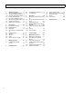
Contents 1 1.1 1.2 1.2.1 1.3 1.3.1 1.4 1.5 1.6 Safety Information . . . . . . . . 5 General Safety Information. . . 5 Safety and Warning Symbols . 6 Generally Applicable Symbols 6 Labels at the Machine. . . . . . . 7 Kleen Sweep 40R/47R Signs . 8 Operation/Safety Information 10 Cleaning Information. . . . . . . 11 Maintenance Instructions . . . 12 2 2.1 2.2 2.3 2.4 Description . . . . . . . . . . . . . 14 Functional Description . . . . . 14 Cylinder Broom . . . . . . . . . . . 14 Side Brush . . . . . .
Safety Information 1 Safety Information 1.1 General Safety Information Apart from the instructions contained in this manual, the general safety instructions and accident prevention regulations, as imposed by law will have to be complied with. Do not put the Manual aside without reading it even if you used similar sweepers before. Take the time to read them now and save time later.
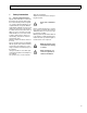
Safety Information 1.2 Safety and Warning Symbols 1.2.
Safety Information 1.3 Labels at the Machine Read and observe operator's Manual (5) The following safety and information signs are legibly attached to the machine. Missing or illegible stickers have to be replaced. Brake (6) Sound power level (7) 86dB (A) Kleen Sweep 40R/47R Folding apron (1) Parking brake(2) Nameplate, front and rear(3) Fig.
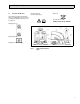
Safety Information 1.3.1 Kleen Sweep 40R/47R Signs Rotating parts (9) 24 V sticker (17) 24 V LDS battery setting (15) Cylinder broom wearing take-up (11) 12 Fig.
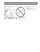
Safety Information Kleen Sweep 40R/47R Signs Continued High-pressure cleaner (13) Battery charging (16) Keep seat hood opened during complete battery charging procedure. This machine operates on 24 Volt DC. Batteries: PN 956740 4 x 6V 275 AH Charger: PN 957731 24VDC, 20 Amp 120VAC Do not clean with highpressure cleaner or vapour jet.
Safety Information 1.4 Operation/Safety Information Vacuum sweepers may be run by qualified personnel only; such personnel will have to have evidenced their qualification for running the machine to the owner or his authorized representative; operators explicitly will have to be instructed by the owner or his authorized representative to use the machine. The machine may be used for cleaning such surfaces approved by the owner or this authorized representative for operation of vacuum sweepers.
Safety Information Warning and instruction labels attached to the machine contain important information about safe operation. Provide for sufficient ventilation when sweeping indoors. Proceed to filter shaking only after having closed the dirt hopper. Do not open the hood with the engine running. 1.5 Cleaning Information The specific safety instructions for handling drive batteries apply. Before proceeding to cleaning of the machine, pull the ignition key. The machine is splash-proof (IPX3).
Safety Information 1.6 Maintenance Instructions A good approach to prevention of accidents is proper maintenance of the machine. Before proceeding to repair or maintenance work remove the ignition key. Use appropriate tools for maintenance, service, setting etc. As far as aspects of safety are concerned, spare parts will have to be at least of the same quality as the genuine spare parts. Switch off the motors before maintaining the machine or replacing parts of it.
Safety Information Before commencing any work on the electrical system disconnect the battery plug of the Kleen Sweep 40R/47R. Do not keep batteries discharged for a longer period; always recharge them as soon as possible. Top with distilled water only. Never refill battery acid in battery cells of perfect condition. Open the hood before charging batteries; generation of explosive gas! Keep batteries dry and clean and clear of soiling such as e.g. metallic dust to avoid leakage current.
Description 2 Description 2.1 Functional Description The side brushes are used to collect dirt at borders and to enlarge the working width as well as to increase the area performance at large spaces. The cylinder broom transports the debris into the dirt hopper. The suction fan vacuums the fine dirt which is separated by a filter system. The air returned into the environment is clean. This sweeper operates dust-free. Fig. 3 Principle of Kleen Sweep 40R/47R 2.
Description 2.4 Filter System / Dust Evacuation The filter system is located in the filter case above the dirt hopper. The suction filter transports the fine dust raised by the cylinder broom to the plate filter and separated there. The fine dusts sets at the outsides of the filter blades. In case of heavy dusting, check and clean the plate filter at regular intervals. 2.6 Steering Steering is controlled from steering wheel to front wheel via fork head. 2.
Battery Systems 3 Battery Systems 1 Before commencing any work on the electrical system disconnect battery plug of the Kleen Sweep 40R/47R. Do not use open flames when handling batteries and especially when checking the battery acid level. Provide for sufficient ventilation in rooms where batteries are charged. Spilled (straight) battery acid must not get into the sewage system before having been neutralised. Comply with the regulations imposed by law and observe local provisions. 3.
First Operation 4 First Operation Before delivery, the machine has been extensively tested and submitted to a functional check. Only qualified personnel of your local contract dealer are allowed to proceed to first operation. After shipping of the machine, we advise your contract dealer. He will contact you to make a date for briefing lessons. 4.
First Operation 4.2 Insert Batteries - Turn engine off and remove key. - Secure machine by engaging the parking brake. - Fold back seat hood. - Insert batteries according to draft into the battery tray: Fig. 6 Fig. 5 18 Insert batteries-A Insert batteries-B - Connect batteries and cable set according to terminal diagram. - Battery type at the low discharge signal sender (see 3.1) - Connect charging plug of the battery connection cable and cable of the charger unit and proceed to initial charging.
Operation 5 Operation 5.1 Kleen Sweep 40R/47R Controls 1. 2. 3. 4. 5. 6. 7. 7 Actuator for folding apron Service brake/parking brake lock Service brake/parking brake pedal Drive pedal, reverse Drive pedal, forward Control panel Seat adjustment 6 5 4 1 3 2 Fig.
Operation 1 Actuator for folding apron to open and close the folding apron for collecting coarse dirt. 2 Service brake/parking brake lock to lock the service brake. If locked, the service brake works as parking brake. Release the lock by depressing the brake pedal (3). 3 20 4 Drive pedal, reverse to change direction to reverse ride and with continuous regulation of velocity at the same time. If the driver lets the pedal go it returns to initial position and the machine slows down to standstill.
Operation 5.2 1. 2. 3. 4. 5. 6. Kleen Sweep 40R/47R Control Panel Suction fan/shaking system knob Cylinder broom lever Side brush lever Key switch Hourmeter Battery charge status 2 3 1 4 6 Fig.
Operation Turn off main broom before jolting. Filter cleaning is improved by interrupting the jolting procedure several times. Turn off the combustion engine of the Kleen Sweep 40R/47R. 1 2 3 1 3 Side brush lever to lift and lower the side brush. - Lower side brush = push lever. Suction fan/shaking system knob - Lift side brush = pull lever. Knob position (from top to bottom position): 1 Shaking system ON (hold knob).
Operation 4 To protect the electromotors, do not start the Kleen Sweep 40R/47R at ambient temperatures of 32°F (0°C) and less. Key switch to switch the electric system on and off, to secure the machine against unauthorised use as well as to acknowledge released seat contact switch. For safety reasons, the Kleen Sweep 40R/47R is equipped with a seat contact switch. Starting the engine is possible only when the driver is seated.
Operation 5.3 Empty Dirt Hoppers Lift cylinder broom before removal of the dirt hoppers. - Fold bow (Fig. 9/3) up and the dirt hoppers (Fig. 9/2) are lowered. - Use the recessed grip (Fig. 9/1) of one of the hoppers to lift it lightly and extract it. 3 1 2 1 Fig. 9 Emptying dirt hopper 1. Recessed grip in dirt hopper 2. Dirt hopper 3. Bow to lift/lower dirt hoppers - Take the hopper at its bow-type handle to disposal and empty. - Empty second dirt hopper as described above.
Operation 5.4 Working With the Kleen Sweep 40R/47R The driver is requested to carefully read this operator's manual. All controls are marked with easy-to-understand symbols that ease familiarization. First driving attempts should be limited to clear areas until you are familiar with all controls and their functions. Please comply with the following safety provisions: When working with the Kleen Sweep 40R/47R all safety measures generally applicable for handling vehicles and fuels have to be observed.
Operation 5.4.2 Sweep 5.4.3 Stop and Park - Lower cylinder broom. - Release parking brake. - Slowly depress drive pedal until desired speed has been attained. - Regularly actuate shaking device to clean filter. - Check contents of the dirt hopper and empty if required. - Release drive pedal (returns automatically into its neutral position and the machine slows down to near standstill) and actuate service brake. - Actuate parking brake. - Lift main and side brush. - Turn key switch to "O".
Technical Data 6 Technical Data Kleen Sweep 40R/47R Dimensions and weights Length with side brush Width with 1 side brush Height above steering wheel Empty weight – serviceable Empty weight – without batteries Driving and sweeping performance Forward speed Reverse speed Sweeping speed (recommended: 2,5 mph (4,0 km/h)) Sweeping track without side brushes - with 1 side brush - with 2 side brushes Theoretical sweeping perf. without side brushes - with 1 side brush - with 2 side brushes Gradability, max.
Technical Data Kleen Sweep 40R/47R Filter system Filtering surface Plate filter Cylinder broom Length Diameter Wearing limit (approx.) Speed Sweeping track Quantity of bristle rows Serial bristling Ground clearance of sealing strips at broom compartment Sealing strips, left right rear Sealing strip, front 28 sq. ft. (m2) piece 30.14 (2.8) 1 in. (mm) in. (mm) in. (mm) rpm in. (mm) 27.6 (700) 13.6 (345) 11.4 (290) 530 ± 20 2.0 + 0.2 (50 + 5) 6 v-shape PES in. (mm) in. (mm) in. (mm) 0.04 (1) 0.
Technical Data Kleen Sweep 40R/47R Side brushes Diameter Speed Serial bristling Dirt hopper Hopper volume Drive wheels Pneumatic tires with tube: tire size Inflation pressure Solid tires Tire Electric drive Service voltage Travel drive assembly Suction fan motor / sweeping motor Total power consumption in. (mm) rpm 18.1 (460) 90 PES cu. ft. 2x1.1 (2x30) in. in. (mm) 4.00 - 4 Ø 9.84 / 2,36 (Ø 250 / 60) DC / V KW KW KW 24 0.6 0.75 1.
Technical Data Kleen Sweep 40R/47R Noise emission The sound power level according to DIN EN ISO 3744, measured under standard operating conditions and maximum volume flow amounts to Vibrations The frequency weighted acceleration measured according to EN 1033 which have an effect upon the lower limbs (hand-armsystem) amounts under normal working conditions The frequency weighted acceleration measured according to EN 1032 which have an effect upon the lower limbs (feet and seat) amounts under normal working
Maintenance/Service 7 Maintenance/Service 7.1 Maintenance Instructions Compliance with our recommendations concerning maintenance work will give you the certitude of having an effective and dependable machine at your disposal. It is better to take precautions than repairing damages – and it saves money! Compliance with our recommendations concerning maintenance work will give you the certitude of having an effective and dependable machine at your disposal.
Maintenance/Service 7.2 Mount/Dismount Cylinder Broom The cylinder broom is accessible from the left side of the machine and is to be dismounted as follows: - Lower cylinder broom - Remove ignition key and protect by engaging parking brake - Open lateral flap - Remove cover - Open locks (Fig. 10/2) by enclosed square spanner (counter-clockwise) - Remove cover (Fig. 10/1) 7.3 1 2 4 2 Fig.
Maintenance/Service Before checking: - Mark level surface for broom adjustment check by chalk. 0.37 in. (10 mm). When exceeding the sweeping track width, the engine protection may be activated. - Lower cylinder broom and let it run dry. - Lift cylinder broom and forward the Kleen Sweep 40R/47R a bit. - With the correct broom adjustment the parallel sweeping marks have to appear on the floor (sweeping track). The sweeping track width is to be 1.97 in. (50 mm) with the Kleen Sweep 40R/47R.
Maintenance/Service 7.4 Sealing Strips for Broom Compartment In order to assure good function of the sweeper, a perfect condition of the sealing strips is required, especially in order to attain the prescribed vacuum in the broom compartment, a clean sweeping result and the less possible wear of the sealing strips (check the sealing strips of the broom compartment for wearing and damages in regular intervals). Replace defective sealing strips.
Maintenance/Service 7.5 Replace Side brush Proceed in inverse order for mounting of the side brush. The side brush is located at the front right of the machine (standard version). Use the lever (Fig. 10/2) to lift and lower the side brush. The side brush is to be lightly inclined in forward and in outward direction. The pivoting area of the side brush arm is limited by stop screws. The side brush is driven by a V-belt. Fitting of a second side brush for specific appliances is possible.
Maintenance/Service 7.6 Dismount Plate Filter Proceed as follows for dismounting of the plate filter: 1 - Open seat hood. - Remove cover. - Loosen fillister head screws (Fig. 16/2) and remove. - Fold back frame with electro-motor (Fig. 16/3). - Hook frame at indicated position (Fig. 16/4). - Remove plate filter (Fig. 16/5). 4 3 2 2 For mounting of plate filter proceed in inverse order. Fig. 16 1. 2. 3. 4. 5.
Maintenance/Service 7.7 Basic Cleaning of Plate Filter Hold the plate filter (Fig. 17/1) in vertical position and let it fall down from a height of 3 ft. (1 m) to the even floor as represented in Fig. 19. 1 The soiled side of the filter has to point to the bottom. Soiled side Clearance approx.31 ft m Floor Fig.
Maintenance/Service 7.8 Electrical System Circuit-breakers and fuses 6 voltage (10A) 3. F4 Shaking function control voltage (5A) 4. F5 not assigned 5. F6 LDS indication (5A) 6. F7 LDS (5A) 7. F11 Shaking motor (30A) 8. F12 Brush motor (60A) 9. F1 Drive control power module (63A) Before leaving the machine unattended, engage the parking brake and remove key. 7.9 Brake It is located in the rear wheels and is actuated via cables. A special adjustment screw is situated at the right-hand rear wheel.
Maintenance/Service 7.10 V-belt drive 1. Tension roller 2. Suction fan V-belt (20Hz) 3. V-belt pulley 4. V-belt for brushes (130 Hz) 5. Side brush V-belt 6. Pulley 7. Cylinder broom V-belt 8. Tensioning roller follower 9. Pulley 10.Tension spring 11.Hexagonal nut 12.Hexagon socket screw 13.Screws Fig.
8 40 Spare part list
Side brush Item PN Qty.
Fr on 42 t
Front wheel drive Item PN Qty. 1 2 3 4 5 6 7 8 9 10 11 12 13 14 15 16 17 18 19 20 21 22 23 24 25 26 27 28 29 30 00137290 00053790 01130010 00747530 01130020 00051500 00046520 00136910 00053730 00051520 01130030 00048410 03002980 00053360 00870090 00135030 00053310 00137930 00746270 03002990 00053650 01130040 01073950 01073960 03003000 01131690 01131680 01131700 00125430 01073970 2 1 1 1 2 2 2 1 1 1 1 1 1 3 13 3 6 1 1 1 2 1 4 4 1 2 2 1 2 1 Hex.
Accelerator Item PN 1 2 3 4 5 6 7 8 9 10 11 12 13 14 15 16 17 18 19 20 21 22 23 24 25 26 27 28 29 30 31 32 33 34 35 36 37 38 39 40 41 42 43 44 45 46 47 48 49 50 51 00051490 01130490 01130500 01130510 01130520 01130530 00154550 01130540 01130550 00875950 00105390 00740090 00053350 00053770 00740310 00053750 00077110 00054890 01130560 01130570 00874720 00975500 01073530 01006210 01006190 03003250 00559670 00083640 03003260 00133830 00053020 00051520 00053730 01130580 01130590 01073650 01130600 00046440 000
Pedal brake Item PN 1 2 3 4 5 6 7 8 9 10 11 12 13 14 15 16 17 18 19 20 21 22 23 24 25 26 01130320 00051510 00053750 00854270 00042900 00124290 01130330 00555130 01055930 01130340 00053110 03003170 00974400 00521270 01130350 00706180 00133830 00557150 00927610 03003180 00108490 00879630 00053100 00074500 00740090 00053350 Qty. 1 5 7 1 2 1 1 1 1 1 1 1 1 1 1 2 2 2 1 1 2 2 2 2 2 2 Pedale brake Hex.nut Washer Bow Washer Socket head cap screw Bolt Packing ring Pull spring Barrier lever Hex.
Steering Item PN 1 2 4 5 6 7 8 9 10 11 12 13 14 15 16 17 18 19 20 21 22 23 24 25 26 27 28 29 30 31 32 33 34 35 36 37 38 01130360 01130370 01130390 01130400 01130410 01130420 00051520 01093180 00044160 01130430 00054690 00053750 00733400 00695300 00051510 01130440 01130450 00521100 01130460 00154410 01130470 00046430 03003230 00045540 00740090 00053160 00053760 00132880 01090960 00535840 00051500 00046520 01130480 01130020 03003240 00123690 00132880 Qty.
Control panel Item PN 1 2 3 4 5 6 7 8 9 10 11 12 13 14 15 16 17 18 00131610 01131620 00052620 01131640 01092720 00745890 00053330 00053730 00021710 01131520 00902200 03003450 00022200 00747400 00975510 00955220 01131640 01131650 Qty. 1 1 5 1 1 1 2 2 1 1 1 1 2 2 1 2 1 1 Control panel, tin plate Control panel, foil Filister head screw Hour meter Gasket Key Hex. nut Washer Key switch Actuating cable Compression spring Holder Hex.
Covering - Seat Item PN Qty.
Motor - Chassis Item PN 1 2 3 4 5 6 7 8 9 10 11 12 13 14 15 16 17 18 19 20 21 22 23 24 25 26 27 28 03003360 00053080 00740090 03003370 00051520 00053730 00126010 00135120 00748300 00053050 00053090 00053750 00051510 01131280 01131290 00874340 00053010 01131300 01092910 03003380 00730940 03003390 01131310 01131670 01131660 00054260 00864520 00042900 Qty. 1 2 6 1 3 2 1 1 1 2 6 6 4 1 1 1 5 1 1 1 4 1 1 1 1 1 1 1 Chassis Hex.bolt Detent washer Battery console Hex.
Electrical equipment Item PN Qty.
Group of main sweeper roller Item 1 2 3 4 5 6 7 8 9 10 11 12 13 14 15 16 17 18 19 20 21 22 23 24 25 26 27 28 29 30 31 32 33 34 35 36 37 38 39 40 41 42 43 44 45 46 47 48 49 50 PN Qty.
51 52 53 54 55 56 57 58 59 60 61 62 63 64 65 66 00053550 01130470 01131000 01131010 01131020 00053020 01131030 01130820 01131050 00053730 01131040 01130910 00243450 00740280 00053330 01130810 1 1 1 1 1 1 1 2 2 8 1 1 1 6 8 1 Screw Bearing bush Pult spring Holder Holder for idler Hex.bolt Bolt Brush apron Strip Washer Brush apron, rear Strip Clamping strip Detent washer Hex.
Manipulation for brush apron - Lifter for sweeping roller Item PN 1 2 3 4 5 6 7 8 9 10 11 12 13 14 15 16 17 18 19 20 21 22 23 24 25 26 27 28 29 30 31 32 33 34 35 36 37 38 39 40 41 42 43 44 01131320 00740090 00053080 01131330 00854420 01131340 00051500 00051520 00526320 01064890 00053330 00123690 00130290 00925430 00740290 01131350 00151440 00151400 00740080 00053090 00041600 01130610 00053750 00051510 00866720 01050160 01131360 01131370 01131380 01131390 00054690 00733400 00695300 00053760 00925420 00132
Filter installation Item PN 1 2 3 4 5 6 7 8 9 10 11 12 13 14 15 16 17 18 19 20 21 22 23 24 25 26 27 28 29 30 31 32 33 34 35 36 37 38 39 40 41 42 43 00051510 01131100 01074080 00042900 00027190 01131110 00053020 00135120 00051520 00451220 01131410 01131120 00045620 01131130 01131140 01130750 00730940 01131150 00420290 01131160 00161240 00740310 00045540 01131170 01131440 01017660 00958770 00071450 00053350 00053750 00053010 00534470 01131180 01131190 01131200 01131210 01130560 01075290 00740360 00023290 0
Dust extraction Item PN 1 2 3 4 5 6 7 8 9 10 11 12 13 14 15 16 17 18 19 20 21 22 23 24 25 26 27 28 29 30 31 32 33 34 01131510 00053350 00740090 00053330 00740280 01092780 00420290 03003430 00903480 00730940 01131840 01131450 03003440 01131460 01131470 00157690 00127360 00871440 00120130 00135790 01131480 00864230 00059080 00070170 00042900 00133700 00131610 00151810 00053750 01131490 00420290 01131500 00104500 01130200 Qty.
Fan bearing Item PN 1 2 3 4 5 6 7 8 9 10 11 12 13 14 15 16 17 18 19 20 21 22 23 00506780 01131220 01131230 00053010 03003350 01131240 00740280 00053330 00706360 00126320 01131250 00538360 01131260 00740090 00022330 00074710 00740290 01131270 00740090 00553690 01130970 00126330 00021800 Qty. 1 1 1 3 1 1 3 3 1 1 1 1 1 1 1 2 1 1 2 2 1 1 1 Threaded pin Rotating fan Shaft Hex. bolt Bearing plate Bearing bush Detent washer Hex.
Dirt hopper - Dirt hopper lifter Item PN Qty. 1 2 3 4 5 6 7 8 9 10 11 12 13 14 15 16 17 18 19 20 21 22 23 24 25 26 27 28 29 30 01130050 00051510 00042900 00878410 00053750 00103300 01130060 01130070 01130080 00101500 01130090 00053100 01130200 01130300 00045540 01130100 01130310 01130110 00750430 01130120 00077110 01130130 01130140 00874930 01130150 01130160 01130170 01130180 00078920 01130190 1 10 12 2 6 6 1 9 9 2 1 2 1 1 4 1 1 1 2 1 1 1 1 2 1 1 4 2 4 2 Holder, l.h. Hex.
Rear wheel - Brake Item PN 1 2 3 4 5 6 7 8 9 10 11 12 13 14 15 16 17 01131060 00135350 01131070 00706370 01130770 01130350 00074710 00053760 01130780 01130790 00281050 01131080 00053730 00051520 01131090 00740290 00021130 Qty. 2 2 2 2 2 2 2 2 2 2 2 2 2 2 2 8 8 Cap Hex. nut Washer Ball bearing Rear wheel Bowden cable for brake Hex. nut Washer Bush Cup head square neck bolt Ball bearing Brake Washer Hex. nut Axle Detent washer Hex.
Lable Item PN Qty.
EC Declaration of Conformity declares under our sole responsibility that the product Kleen Sweep 40R/47R Type: HM40B/HM47B/HM40BQP HM47BQP/HM40QP/ HM50QP For the relevant implementation of the safety and health requirements mentioned in the Directives, the following standard(s) and/or technical specification(s) has (have) been respected: EN 60335-2-72 EN 61000-6-3 EN 61000-6-2 Addison (Illinois), 30th Sept.
LIMITED WARRANTY Minuteman International, Inc. warrants to the original purchaser/user that this product is free from defects in workmanship and materials under normal use and service for a period of one year from date of purchase. In addition, Minuteman International, Inc. will, at its option, honor labor warranty claims for the first 6 months from date of sale, provided such claims are submitted through and approved by factory authorized repair stations. Minuteman International, Inc.