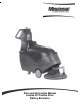
Parts and Instruction Manual Lumina 20 Traction Drive Battery Burnisher
This manual is furnished with each new MINUTEMAN Lumina 20. This provides the necessary operating and preventive maintenance instructions. Operators must read and understand this manual before operating or servicing this machine. This machine was designed to give you excellent performance and efficiency. For best results and minimal cost, please follow the general guidelines below: · Operate the machine with reasonable care.
Parts and Instruction Manual
Table of Contents IMPORTANT SAFETY INSTRUCTIONS .............................................................................................. 1 Operating Instructions ....................................................................................................................... 2 Inspection ........................................................................................................................................ 2 Electrical .............................................................
IMPORTANT SAFETY INSTRUCTIONS CAUTION: Operators must read and understand this manual before operating or maintaining this machine. Keep hands and feet clear of moving parts while machine is in operation. Disconnect the power to the machine by pressing the Red Emergency Disconnect Button when charging batteries or during installation or removal of pads. During operation, loose objects on the floor can become dangerous projectiles if struck by the high speed pad.
Operating Instructions Inspection Carefully unpack and inspect your burnisher for shipping damage. Each unit is tested and thoroughly inspected before shipment; any damage is the responsibility of the delivery carrier who should be notified immediately. Electrical This machine is battery operated and designed to operate on 36 volts DC (3) 12 volt batteries. Batteries Burnishers are shipped with batteries. (3 required) Part No. 956210 12V 210AH 20 Hr. Rate We do not recommend mixing AMP hour capacities.
After Use To raise the pad driver, push down until the pedal arm engages into the pedal catch. Turn machine off by turning the key switch on the control panel. Machine can be cleaned with a mild detergent and a damp cloth. Batteries should be charged after each use or when the battery condition meter shows a low charge. Once the battery charger reads 0 amps, the batteries are recharged. This should take approximately 8 hours if the batteries are completely discharged.
Pad Installation The red emergency disconnect button and the key switch must be in the OFF position before installation and the pad driver assembly in the RAISED position. Remove center cup locking device by gripping on outer edges and turning clockwise. NOTE: Center cup cannot be pulled out; it must be unscrewed. After removing used pad, place new pad on pad driver assembly using outer flange of pad driver to center the pad. Push centering locking cup through the pad and into the pad driver assembly.
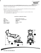
Machine Overview A C B D E F G H A B C D E F I J K L PAD PRESSURE ADJUSTMENT BAIL LEVER DUST BAG DASHBOARD CONTROL PANEL EMERGENCY BELLY BAR STOP CARBON BRUSH INDICATOR Parts and Instruction Manual G H I J K L EMERGENCY STOP BUTTON POWER CONNECTOR CIRCUIT BREAKER, 70 AMP CIRCUIT BREAKER, 3 AMP CIRCUIT BREAKER, 18 AMP FOOT PEDAL Page 5
Dashboard Control Panel A D A B C D E F B E C F ON / OFF KEY SWITCH TRACTION DRIVE DIRECTION INDICATOR TRACTION DRIVE DIRECTIONAL SWITCH BATTERY GUAGE TRACTION DRIVE SPEED CONTROL PAD PRESSURE GUAGE Parts and Instruction Manual Page 6
Exploded Views Base Assembly Parts and Instruction Manual Page 7
Base Assembly BOM BILL OF MATERIAL ITEM PART NO. REQ'D DESCRIPTION 1 200126 2 MOUNT, TRANSAXLE 2 200154 1 PANEL COVER WELDMENT 3 172167 2 CASTER, 3-1/2 POLYURETHANE 4 210141 2 WHEEL 8 X 1.5 X .75 BORE 5 260224 1 18" HOSE 6 260536 1 BASE PLATE WELDMENT 7 260541 1 REAR HANDLE BRKT 8 260549 1 PRESSURE ADJ ASSEMBLY 9 260579 1 TOOL CLIP, 1.
Mainframe Assembly Parts and Instruction Manual Page 9
Mainframe Assembly BOM BILL OF MATERIAL ITEM NO. PART NO. QTY. DESCRIPTION 1 260536 1 BASE PLATE W ELDMENT 2 260577-1 1 SW ITCH INTERLOCK BRACKET 3 711503 2 W SR, FLAT#10 4 711350 2 NUT NYLOC 10-32 5 740830 1 SW ITCH SPST NC CONTACT 6 711501 2 W SR-FLAT # 6 7 710307 2 SCR-MC 6-32 X 1.0 ST PL PAN HD 8 711430 1 NUT-TINNERMAN TW IN 6-32 9 260522 1 SPRING GUIDE 10 670605 2 ROLLER PIN 11 711506 8 W SR-FLT .344 X .690 X .062 STL ZINC 12 711721 4 RET RING-E TYPE .
Housing Assembly Parts and Instruction Manual Page 11
Housing Assembly BOM ITEM 1 2 3 4 5 6 7 8 9 10 11 12 13 14 15 16 17 18 19 20 21 22 PART NO. 260501 260502 260503 260504 260560 260590 260592 260596 310008 450037 450081 450207 710180 711160 711228 711373 711374 711506 711516 711519 828970 831001 Parts and Instruction Manual BILL OF MATERIAL REQ'D DESCRIPTION 1 FIXED TOP COVER 1 MOVING TOP COVER 1 BAG COVER 1 FILTER COVER WELDMENT 1 HINGE 9.
Pad Driver Assembly Parts and Instruction Manual Page 13
Pad Driver Assembly BOM BILL OF MATERIAL - 260610 ITEM PART NO. REQ'D DESCRIPTION 1 260573 1 MOTOR GRILL ASSY 2 260597 1 KEY, 3/16 X .906 3 260611 1 PAD DRIVER SHROUD - 20" 4 260615 1 MOTOR PLATE WELDMENT - NEW 5 260616 1 DUST SKIRT - NEW 6 260619 2 PAD DRIVER STRAP 7 670075 1 PAD DRIVER ASSY 8 710857 1 SCR-SC 5/16-24 X 1.00 9 711124 2 PAN HEAD ST #10 X .37 NI 10 711505 3 WSR-FLAT 1/4 11 711512 4 WSR-FLAT .75X1.37X.08 12 711516 1 WSR- FLAT .31 X 1.25 X .
Pressure Control Assembly ITEM 1 2 3 4 5 6 7 8 9 10 11 12 13 14 BILL OF MATERIAL - 260549 PART NO. REQ'D DESCRIPTION 260066 1 OILITE BUSHING 260547 1 PRESS ADJ MOUNT WELD 260554 1 PRESS ADJ SCREW 260557 1 PRESS ADJ SLIDE 260562 1 PRESS ADJ RET BRKT 260563 1 PRESS ADJ RET BRKT 260564 1 ROLL PIN 3/16"X3/4" 710353 4 SCR-MC 10-32 X .37 ST PL 711391 1 NUT-HEX JAM 3/8-16 ST PL 712536 1 SCR-MC 10-24 X .
Electrical Assembly BILL O F M ATERIAL - 260588 IT EM P ART NO . REQ 'D DES CRIP TIO N 1 260542 1 B A CK P A NE L W E LDM E NT 2 710356 2 S CR-M C 10-32X.
Console Assembly Parts and Instruction Manual Page 17
Console Assembly BOM ITEM 1 2 3 4 5 6 7 8 9 10 11 12 13 14 15 16 17 18 19 20 21 22 23 24 25 26 27 28 29 30 31 32 33 34 35 36 37 38 39 40 41 42 43 44 45 46 BILL OF MATERIAL - 260583-1 PART NO.
Dashboard Assembly ITEM 1 2 3 4 5 6 7 8 9 10 BILL OF MATERIAL - 743830-1 PART NO.
Wiring Diagram Parts and Instruction Manual Page 20
Parts and Instruction Manual Page 21
Parts and Instruction Manual Page 22
Minuteman International Made Simple Commercial Limited Warranty REVISION F EFFECTIVE 6/1/2009 Minuteman International, Inc. warrants to the original purchaser/user that the product is free from defects in workmanship and materials under normal use. Minuteman will, at its option, repair or replace without charge, parts that fail under normal use and service when operated and maintained in accordance with the applicable operation and instruction manuals.