
Operating instructions

4
PP
PP
P
AD PRESSURE AD PRESSURE
AD PRESSURE AD PRESSURE
AD PRESSURE
ADJUSTMENTSADJUSTMENTS
ADJUSTMENTSADJUSTMENTS
ADJUSTMENTS
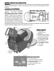
The pad pressure adjust knob is located on the top of the control console. Counter-clockwise rotation
increases pad pressure, the opposite rotation decreases. Different floors, conditions, and pads
produce carying pad load conditions. Ideal burnishing conditions are maintained while the operating
range meter remains in the Green Zone. If the meter reads in the Red Zone decrease the pad
pressure. When the machine is operated in the Red Zone for a long period of time motor overload
will occur and the 70-amp circuit breaker for the motor will trip. If the motor circuit trips:
1. Check pad condition.
2. Decrease pad pressure.
3. Reset circuit breaker.
CIRCUIT BREAKER PROTECTIONCIRCUIT BREAKER PROTECTION
CIRCUIT BREAKER PROTECTIONCIRCUIT BREAKER PROTECTION
CIRCUIT BREAKER PROTECTION
70 amp circuit breaker protects pad driver motor form excessive overload conditions.
3 amp circuit breaker protects control circuits against possible electrical shorts.
If either circuit breaker trips, first determine the cause and correct the condition before resetting the
breakers.
CARBON BRUSH REPLACEMENTCARBON BRUSH REPLACEMENT
CARBON BRUSH REPLACEMENTCARBON BRUSH REPLACEMENT
CARBON BRUSH REPLACEMENT
Design life of carbon brushes is between 1800-2000 hours. Replace brushes if worn to 3/8" or less,
broken, or chipped. All carbon brushes should be replaced when motor is serviced. Four (4) are
required, P/N 572003. Red indicator on control panel (above Emergency Disconnect Button, below
the Dashboard) will glow when carbon brush service is required.
CARBON BRUSH SERVICECARBON BRUSH SERVICE
CARBON BRUSH SERVICECARBON BRUSH SERVICE
CARBON BRUSH SERVICE
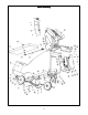
1. Disconnect batteries from machine.
2. Remove two screws that hold dust control housing and motor cover to motor.
3. Blow out top of motor with air line.
4. Loosen screw and remove carbon brush lead.
5. Slide brush spring off the back of carbon brush and remove brush.
6. Reverse order for installation of new carbon brushes.
Pad InstallationPad Installation
Pad InstallationPad Installation
Pad Installation
The red emergency disconnect button and power must be in the OFF postion before intallation and
the pad driver assembly in the RAISED position. Remove center cup locking device by gripping on
outer edges and turning clockwise.
NOTE: NOTE:
NOTE: NOTE:
NOTE: Center cup cannot be pulled out; it must be unscrewed.
After removing used pad, place new pad on pad driver assembly using outer flange of pad driver to
center the pad. Push centering locking cup through the pad and into the pad driver assembly. The
ratchet teeth on the center cup will engage into the pad driver assembly and should be pushed in as
far as possible. If further tightening is needed, rotate the center-locking cup counter-clockwise.