Continuous Power Series User’s Manual MCP 6001 MCP 10001
TABLE OF CONTENTS 1. INTRODUCTION 1.1 Explanation of symbols 1.2 System description 1.3 Product specification Electrical specifications Operating environment Mechanical specification 1.4 Switches and displays 1.5 Safety 1.6 Communication port 1.7 RS232 interface 2. INSTALLATION AND OPERATION 2.1 Unpacking and inspection 2.2 Installation 2.3 Wiring description 3. TROUBLESHOOTING APPLICATION NOTES 1. START UP 2. OUTPUT VOLTAGE SETTING 3. DISPLAYS AND ALARMS 1. Load level and battery capacity 2.
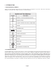
1. INTRODUCTION 1.1 EXPLANATION OF SYMBOLS Some or all of the following symbols may be used in this manual or may appear on your unit. Please take a moment to familiarize yourself with these symbols and their associated meanings. 1.2 SYSTEM DESCRIPTION The MCP SERIES UPS is an advanced True On-Line sinewave Uninterruptible Power Supply (UPS) with automatic bypass.
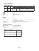
1.3 PRODUCT SPECIFICATIONS ELECTRICAL SPECIFICATIONS Input Model No. Power Rating Freq. (Hz) MCP 6001 6KVA 4.2KW 50/60 170-276 VAC MCP10001 10KVA 7KW 50/60 170-276 VAC Voltage Output Current 33A 56A Voltage 120, 120/120, 208, 120/208, 240, 120/240V 120, 120/120, 208, 120/208, 240, 120/240V Current 50, 25/25, 28.8, 25/28.8, 25, 25/25A 83.3, 41.7/41.7, 48.1, 41.7/48.1, 41.7, 41.7/41.
MCP Control Panel MCP 6001 Front View MCP 10001 Front View MCP 6001 Rear View MCP 10001 Rear View 1.4 SWITCHES AND DISPLAYS ◆ ON/OFF switches: Push the “ ON “ button until the alarm sounds to turn on UPS. Push “ OFF “ button until the alarm sounds to turn off UPS. ◆ LINE LED: This light is on when the incoming AC line is normal. ◆ BYPASS LED: T his light is on when the UPS is providing power directly from the incoming AC line through the bypass route.
1.5 Safety IMPORTANT SAFETY INSTRUCTIONS This manual contains important instructions for MCP SERIES series that SHOULD BE FOLLOWED DURING INSTALLATION AND MAINTENANCE of the UPS and the batteries. The sound pressure level at the operator’s position is equal to or less than 60dB(A). IMPORTANT SAFETY INSTRUCTIONS SAVE THESE INSTRUCTIONS! WARNING: CHANGES OR MODIFICATIONS TO THIS UNIT NOT EXPRESSLY APPROVED BY THE PARTY RESPONSIBLE FOR COMPLIANCE COULD VOID THE USER’S AUTHORITY TO OPERATE THE EQUIPMENT.
CAUTIONS: The UPS contains voltages which are potentially hazardous. All repairs should be performed by qualified service personnel. The UPS has its own internal energy source (battery). The output may be ‘hot” even when the UPS is not connected to the AC supply. The voltage the internal batteries create is: Model Number MCP6001 MCP10001 ◆ ◆ ◆ ◆ ◆ ◆ ◆ ◆ ◆ Battery Voltage 240 VDC For the safety of the UPS, do not connect an imbalanced load.
1.6 COMMUNICATION PORT The UPS provides an RS232 serial port to communicate with a host computer. The host computer can monitor the UPS through this RS232 communication port. The data format of RS232 is as follows: Baud Rate : 2400 bps Data Length : 8 bits Ending Code : 1 bit Parity Bit : none 1.7 RS-232 IINTERFACE The following is the pin assignment and description of DB-9 connector: Pin # 2 3 5 Description RS232 Rx RS232 Tx Ground I/O input output input 2. INSTALLATION AND OPERATION 2.
2.3 WIRING DESCRIPTION The wiring method for the MCP SERIES is shown in Figure A. Figure A - Wiring Diagram for MCP 6001, & MCP10001 REAR VIEW Wiring Instructions: 1. Utility panel circuit breaker required is 35A or larger 2. Utility wire guage must be 8 guage or larger. 3. Connect utility per drawing. 4. Connect output load connections and jumper wires for correct voltages per drawings. 5. Use proper size AWG wires for all connections.
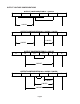
OUTPUT VOLTAGE CONFIGURATIONS L1 OUTPUT CONFIGURATION #1 = 120VAC L2 L3 L4 N G 120VAC L1 OUTPUT CONFIGURATION #2 = 120VAC / 120VAC L2 L3 L4 N G 120VAC 120VAC L1 OUTPUT CONFIGURATION #3 = 208VAC L2 L3 L4 N G 208VAC L1 OUTPUT CONFIGURATION #4 = 120VAC / 208VAC L2 L3 L4 N 120VAC 120VAC 208VAC Page 8 G
L1 OUTPUT CONFIGURATION #5 = 240VAC L2 L3 L4 N G 240VAC L1 OUTPUT CONFIGURATION #6 = 120VAC / 240VAC L2 L3 L4 N 120VAC G 120VAC 240VAC ◆ ◆ ◆ When using an isolation tranasformer, ensure that the load is balanced. When using #6 AWG wire 2 in. are required for wire bending space opposite the terminals. 1 1/2 in. for #8 AWG. 3 in. for #3 AWG and #4 AWG. 3 1/2 in. for #2 AWG. For 6KVA output configuration #1, #2, #3, #4, #5, #6, and #7 use #6 AWG, 75ºC copper wire.
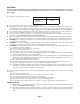
3. TROUBLESHOOTING The TROUBLESHOOTING CHART covers most of the difficulties you may encounter under normal working conditions. TROUBLESHOOTING CHART Problem Possible cause Problem “FAULT” LED lights, alarm beeps continuously UPS failure Call for service Backup time is less than the rating Battery is not fully charged, dead battery, charger failure Recharge battery for at least 6 hours, retest the backup time.
APPLICATION NOTES 1. START-UP 1. Turn on Input breaker and the Battery breaker (10KVA) on the rear panel after checking the power wiring. The cooling fans should be rotating and the control panel should show the display as below. Figure 1.1-1 Bypass Mode (Load LED display depends of load level) 2. Then press the “|” button. After 10 seconds, the control panel will become what is shown in Fig. 1.2-1. 3. Turn on the output breaker located on the rear panel to provide power to the load. Figure 1.
3. DISPLAYS AND ALARMS 1. Load level and battery capacity is represented by 5 LEDs on the upper half of control panel (the 6th LED means FAULT). (A). When the UPS is in the On-Line mode, the 5 LEDs represent load level. They denote 0%~35%, 35%~55%, 55%~75%, 75%~95% and 95%~105% (from buttom to top) of maximum load capacity. If the load amount reaches 105%~130%, the UPS is in overload such that the 6 LEDs would illuminate simultaneously. The UPS will then switch to BYPASS mode10 seconds later.
4. An alarm sounds continuously during an over-temperature condition. Figure 3.4-2 Battery Mode Figure 3.4-1 Line Mode 5. Display and alarm for overload. The alarm will sound once every 0.5 seconds during an overload condition. While in inverter mode, the alarm can be silenced by pressing the “OFF” button. In the Battery Test mode, the UPS will go to BYPASS immediately and the alarm will sound continuously. Figure 3.5-2 Inverter Mode Figure 3.5-1 Bypass Mode Figure 3.5-4 Battery Test Figure 3.
7. Alarm for abnormal input voltage. A) During Start-up, the Line LED will flash if the input voltage drops below 185V or above 261V. Pressing the “|” button will not switch the UPS from Bypass Mode to Inverter Mode. (B)During operation, the UPS will switch from Inverter Mode to Battery Mode if the input voltage drops below 170V or above 276V. (C) In Battery Mode, the UPS does not change mode even if the line power recovers when voltage is below 170V or above 276V.
10. Inverter STS short alarm. The system will detect if the inverter STS is shorted when the “ON” button on the control panel is pressed. If the STS short is detected, the display shows as below and the alarm sounds continuously. Figure 10.1 Inverter STS short alarm LIMITED PRODUCT WARRANTY Para Systems Inc.
DECLARATION OF CONFORMITY Application of Council Directive(s): 89/336/EEC, 7/23/EEC Standard(s) to which Conformity is Declared: EN50091-2, EN50091-1_ Manufacturer’s Name: Para Systems, Inc. (MINUTEMAN UPS)_ Manufacturer’s Address: 1455 LeMay Drive Carrollton, Texas 75007 USA Type of Equipment: Uninterruptible Power Supplies (UPS) Model No: MCP 6001, MCP 10001__ Year of Manufacture: Beginning 1998_ I, the undersigned, hereby declare that the equipment specified above conforms to the above Directive(s).
Notes:
Para Systems, Inc. 1455 LeMay Dr. Carrollton, TX 75007 Phone: (972) 446-7363 Fax: (972) 446-9011 Internet: www.minutemanups.com UPS Sizing: sizemyups.