® User's Manual
EXTENDED RUN TIME SERIES XRT Series of Battery Packs I. INTRODUCTION............................................................... 2 Safety Cautions II. INSTALLATION ................................................................ 5 Cautions ............................................................................ 5 Installation Placement ....................................................... 6 Installation, Step-by-step ................................................... 7 Storage..............
Thank you for purchasing the Minuteman XRT series of external Battery Packs for your MINUTEMAN Uninterruptible Power Supply system. It has been designed and manufactured to provide many years of troublefree service. The batteries used in the XRT series are sealed, maintenance-free, leadacid batteries, with the electrolyte completely absorbed in the plates and separator material. For maximum battery life, the battery packs should be kept as cool as practical indoors.
RECEIVING INSPECTION Upon receipt of the Battery Pack, check the outer packaging for any external damage that may have been caused by the carrier. After removing your Minuteman XRT Battery Pack from its carton, inspect the unit again for any damage that may have occurred in shipping. Notify the carrier and place of purchase immediately if any damage is found. Warranty claims for damage caused by the carrier will not be honored.
CAUTION: AVOID INSTALLING THE BATTERY PACKS IN LOCATIONS WHERE THERE IS WATER OR EXCESSIVE HUMIDITY. CAUTION: DO NOT ALLOW WATER OR ANY FOREIGN OBJECTS TO GET INSIDE THE BATTERY PACK. DO NOT PUT OBJECTS CONTAINING LIQUIDS ON OR NEAR THE UNIT. INSTRUCTIONS IMPORTANTES CONCERNANT LA SÉCURITÉ: CONSERVER CES INSTRUCTIONS. CETTE NOTICE CONTIENT DES INSTRUCTIONS IMPORTANTES CONCERNANT LA SÉCURITÉ. ATTENTION: UNE BATTERIE PEUT PRÉSENTER US RISQUE DE CHOC ÉLECTRIQUE, OU DE BRULURE PAR TRANSFERT D'ENERGIE.
CAUTIONS: It is recommended that you turn the UPS off and disconnect it from the AC wall outlet prior to connecting or disconnecting the battery terminals. If battery packs MUST be changed while the UPS is supplying power to protected equipment, they can ONLY be changed while the AC line is supplying power. DO NOT attempt to replace batteries or battery packs while the UPS is in battery backup mode. Be extremely careful while plugging or unplugging additional battery packs.
INSTALLATION PLACEMENT: Select the location of the battery pack(s) with care and use the following precautions; 1. 2. 3. 4. Avoid locations near heating devices. Avoid locations near water or excessive humidity. Do not expose the Battery Pack to direct sunlight. Route power cords where they cannot be walked on or damaged. The battery packs and UPS unit must be placed on a level, smooth surface and cannot be stacked more than 4 units high. All battery packs that exceed 80 Lbs.
A suggested layout for stacking multiple battery packs should be determined by the technician performing your installation. Each installation is unique to the job site and should be reviewed and planned PRIOR to moving this heavy equipment. Measuring the equipment and the installation site may be required. Always make sure your floor strength is sufficient to handle extreme weight when installing this heavy equipment.
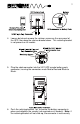
4. Loosen but do not remove the retainer screws on the rear panel of the UPS, then drop the retainer bracket down. This retaining bracket is not present on all models. 5. Plug the cable connector into the XRT UPS remote battery pack connector, insuring the connectors mate Red to Red and Black to Black. 6. Push the retaining bracket "up" to secure the battery connector in place and retighten the screws (not required on all models).
installed all of the way into the receptacle. Upon successful connection, verify that the bracket will not allow removal of the connector. For multiple battery pack installation, each battery pack is "daisy chained" in a similar fashion, with the cable from the last battery pack connected to the previous pack. Remove the protective strips only from the battery connectors that you use.
4. In order to locate the terminal block on the battery pack you will need to remove the top cover of the battery pack. Note: On some models, the terminal block may be accessed from the rear panel of the battery pack. Warning: When the cover is removed, danger of shock exists from the batteries. Use extreme caution. 5. Connect the positive connection of the battery pack to the positive connection on the UPS. Connect the negative connection of the battery pack to the negative connection on the UPS.
7. Reinstall the cover plates on the back of the UPS if they were removed. 8. The unit is now ready for normal startup procedures as described in the UPS owner's manual. Make sure all switches and breakers on all units installed are placed in the ON position. Failure to have all of the switches in the ON position may render the UPS inoperable or reduce the runtime when multiple battery packs are installed.
Note: On all MINUTEMAN Plug and Play configurations, the red connector is battery positive and the black connector is battery negative. 5. After all connections have been made and verified to be correct, reinstall the cover on the battery pack if it was removed. Insure all cover screws are installed. 6. Reinstall the cover plates on the back of the UPS if they were removed. 7. The unit is now ready for normal startup procedures as described in the UPS owner's manual.
If the Battery Pack requires service: Before returning a defective unit to Minuteman, please follow the standard procedures listed below. 1. Call your dealer for assistance. If you cannot reach your dealer, or if the problem cannot be resolved, call or fax Minuteman's Technical Support department at the following numbers: Voice - 972-446-7363, Fax - 972-446-9011 E-Mail - support@minuteman-ups.com 2. Please have the following information available BEFORE calling technical support. A.
4. Include a letter with your name, address, daytime phone number, RMA #, a copy of your original sales receipt, and a brief description of the trouble. 5. Mark the RMA # on the outside of all packages. The factory cannot accept any package without the RMA # marked on the outside. 6.
LIMITED PRODUCT WARRANTY Para Systems, Inc. (Para Systems) warrants this equipment, when properly applied and operated within specified conditions, against faulty materials, or workmanship for a period of three years from the date of original purchase by the end user. For equipment sites within the United States and Canada, this warranty covers repair or replacement of defective equipment at the discretion of Para Systems. Repair will be from the nearest authorized service center.
EXCEPT AS PROVIDED ABOVE, IN NO EVENT WILL PARA SYSTEMS BE LIABLE FOR DIRECT, INDIRECT, SPECIAL, INCIDENTAL, OR CONSEQUENTIAL DAMAGES ARISING OUT OF THE USE OF THIS PRODUCT, EVEN IF ADVISED OF THE POSSIBILITY OF SUCH DAMAGE. Specifically, Para Systems is not liable for any costs, such as lost profits or revenue, loss of equipment, loss of use of equipment, loss of software, loss of data, cost of substitutes, claims by third parties, or otherwise.