SPORTSART C520U UPRIGHT BIKE TABLE OF CONTENTS 1. INTRODUCTION.................................................................................................... 1 2. IMPORTANT SAFETY PRECAUTIONS ............................................................... 2 3. ASSEMBLING YOUR BIKE List of Parts............................................................................................................ 4 Unit Assembly Procedure.............................................................................
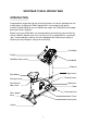
SPORTSART C520U UPRIGHT BIKE INTRODUCTION Congratulations on purchasing one of the finest pieces of exercise equipment on the market today, the SportsArt C520U Upright Bike. Constructed of high quality materials and designed for years of trouble-free usage, the C520U will be an integral part of your fitness regimen. Before using your C520U bike, we recommend that you familiarize yourself with this Owner's Manual.
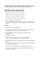
Your SportsArt bike was designed and built for optimum safety. However, certain precautions apply whenever you use your bike. Please read the entire manual before assembly and operation. Also, please note the following safety precautions: IMPORTANT SAFETY PRECAUTIONS Please read and observe the following safety guidelines: ‧Keep this owner's manual for future use and reference. ‧Read this owner's manual and follow the instructions. ‧Assemble and operate the bike on a solid, level surface.
‧The weight limit for this bike is 150 kgs (330 lbs). Caution Before beginning any exercise program, you should consult with your doctor. It is recommended that you undergo a complete physical examination.
ASSEMBLING YOUR BIKE Thank you for purchasing our product. Even though we go to great efforts to ensure the quality of each product, occasional errors and/or omissions do occur. Please contact your dealer if you find this product to be defective or missing a part. Please read this owner's manual and follow the instructions. IMPORTANT: The packing for this bike was designed to protect it during shipment. Please store the original packing in a safe place in case you need to ship the unit in the future.
1. Pedestal 2. Pedestal cover 3. Right pedal 4. Main frame 5. Rear support 6. Rear support cover 7. Left pedal 8. Seat bottom 9. Handlebar mount lower cover 10. Handlebars 11. Handlebar mount upper cover 12.
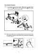
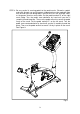
Unit Assembly Procedure STEP 1. For the following, please refer to Figure 1. Secure the rear support bar to the unit frame. Insert screw sockets E into the holes. Loosen screws A, B, C, D to make room for the rear support cover. Slide the rear support cover into place. Then secure those screws. Fig.1 Note: Hold the rear support cover at a 5-degree angle while inserting it into the frame. Press lightly at G to insert the top into both sides of the cover.
STEP 2. First slip the pedestal cover onto the pedestal. Position the data cable for safety. Then insert the pedestal onto its mount. Lightly tighten bolts A into the lower holes (at position D) to secure the pedestal. Do not fully tighten these bolts. Pull the pedestal downward until the other holes come into place and bolts can be secured. See Figure 3. Tighten bolts in position C as shown in Figure 4. Then secure bolts in positions A and B, as shown in Figure 4.
STEP 3. Hold the handlebars in place on the frame while securing the handlebar bolts. Then secure the upper and lower handlebar mount covers. See Figures 7 and 8. Fig.7 Fig.
STEP 4. Be very careful in securing pedals to the pedal cranks. Otherwise, pedals and crank threads can easily become stripped and must be replaced. Note that left and right side designations refer to the user's left and right sides, as the person exercises on the bike. Put the pedal marked "R" on the right crank fitting. Turn the pedal stem clockwise by hand until you feel it smoothly thread into place. Then use the pedal wrench to secure the pedal firmly on the crank.
STEP 5. Secure the seat bottom into place. See Figure 10. Flat washer Spring washer Nut Fig. A Fig.
STEP 6. Level the bike as follows to ensure that it does not wobble. Rotate rubber leveler feet up or down as needed to stabilize the bike. Then rotate leveler nuts upward, against the frame, to secure this position. See Figure 11. Fig.
Seat Adjustment Procedure To raise the seat height, turn the seat adjustment knob A counterclockwise to loosen it, then pull the seat up. See Figure 12. Fig.12 To lower the seat height, do the following: 1. Pull the adjustment knob A out, toward the pedestal, then push the seat down. 2. Release the adjustment knob when the seat is at the proper position. 3. Turn the adjustment knob clockwise to secure it in place. See Figure 13. Fig.
Seat Forward/Backward Adjustment 1. Push the seat adjustment lever downward as shown in Fig. 14. 2. Move the seat bottom forward or backward as desired. Then pull the seat adjustment lever upward to secure the seat in place. See Fig. 15. Fig.14 Fig.
UNDERSTANDING THE C520U DISPLAY CONSOLE Display Windows The C520U is designed for user convenience. With better feedback about your workout, you get better results. The following explains the display key and window functions. Please read this manual, understand the display functions, and thereby get optimum enjoyment and benefit from this product.
Display Function Overview ˙Windows: ■ 65% HR TARGET - shows the optimum heart rate zone for weight loss. ■ HEART RATE - shows actual heart rate. ■ 80% HR TARGET - shows the optimum heart rate for cardio workout. ■ WORKOUT ILLUSTRATION - shows workout profiles and workout prompts. ■ FEEDBACK WINDOW - shows workout prompts and workout feedback. ■ LEDs - light to indicate active programs, active feedback, scan mode, selection confirmation, and body areas being exercised.
2. In any circumstance, Hold the STOP key for three seconds to go back to the start up banner screen. ˙Display Setting Ranges ˙WORKOUT LEVEL (resistance): 1 ~ 20 ˙TIME: 00~99:59; setting range: 5:00 ~ 99:00. (After 99:00, 0 appears) ˙DISTANCE: 0.01-9999 Km/Mile ˙CALORIES: 0~9999 K-CAL ˙CAL/Hr (calories per hour): 0.0~999.9 K-CAL ˙RPM (rotations per minute): 0~200 (countable) ˙HEART RATE (range): 40-250 ˙WATTS: 0~9999 ˙SPEED: 0~55.9 Mile/H / 0~90 Km/H (1 Km=0.62137 Miles; 1 Mile=1.
Operating the C520U Bike Start: Press the START key or press the QUICK START key, or simply start pedaling (over 30 RPM). The startup banner "SPORTSART─C520" appears. QUICK START 1. At the startup banner, press the QUICK START key. Quick start mode uses the default assumption of a 35-year-old, 165-lb/75-Kg user to calculate calorie and other feedback values. Time counts upward. Resistance starts at level one and can be adjusted during exercise. 2.
DISTS - 15.8 CALS - 1020 ˙ Use any <▲> or <▼> key to choose a user ID. Then press ENTER to confirm your choice. (B) To set up a personalized user ID This function allows users to establish a user ID with up to 11 characters. ˙ When an USER ID appears, press the CHANGE key continuously for three seconds to change the USER ID. The following appears: E N T E R N A M E ˙ Press <▲ /▼ > keys to choose an alphabetical character. Then, press the ENTER key to confirm your selection.
3. To select a workout program (A) Press the workout program key. The related program indicator lights up. Then press the ENTER key to confirm your choice and proceed to the TME setting. (B) When exercising, press the Zone TRAINER key to enter the heart rate control (HRC) mode. 4. Time setting (A) Press the < ▲ > or < ▼ > key to select an appropriate duration for your workout. Then press the ENTER key to confirm your choice. 5. Changes during a workout (A) Resistance can be changed as you exercise.
Program Functions 1. TRACK The TRACK function represents a running track. One lap is 400 Meters or 1/4 Mile. The user can manually adjust resistance and stride. 2. HILL The HILL program contains three hill patterns to choose from. A different pattern appears each time the HILL key is pressed: HILL-1, HILL-2, HILL-3. 3. RANDOM The RANDOM program contains a random selection of workout patterns. A new pattern appears each time the RANDOM key is pressed. 4.
(B) At the start of the exercise or while exercising, if the user's heart rate is not detected, the message "NO HEART RATE READING, PLEASE CHECK TRANSMITTER" appears. At this time, while no heart rate is detected, resistance can only be adjusted manually.
Internal Settings Internal settings determine basic operating conditions, for example, units of measure. To access internal settings, at the startup banner『 SPORTSART-C520』 , press and hold the CHANGE key for three seconds. 1. Follow the steps below to change internal settings. (1) Determining Metric/American standard units of measure The feedback windows show the present setting.
USER PARAMETER SETTING To check system default settings, at initial setting stage (select PROGRAM or QUICK START), hold the CHANGE key for 3 seconds: (1) Unit of Speed (MPH or KPH): press ▲/▼ keys to change the setting. Press ENTER to confirm your choice and to see the next setting. You may also press STOP to leave this setting. (2) The next setting, "DIST", shows the total accumulated distance. The unit of distance is either in Miles or Kilometers, depending on the speed setting selected previously.
MAINTAINING THE C520U BIKE The Sports Art C520U requires little maintenance but regular cleaning is recommended to keep your bike at peak performance. Before your workout, use a dry cloth to clean the surface of the display. NOTE: NEVER POUR LIQUIDS ON THE DISPLAY. To clean plastic parts, use a mild detergent, and make sure the unit is completely dry before operating it. It is recommended that you keep all liquids away from the unit during operation.
TROUBLESHOOTING Procedure to Replace a Fuse To remove a fuse, press the fuse cap in, then turn it counterclockwise. The fuse and cap will spring out. Remove the burnt fuse from the fuse cap. Insert a new fuse of the same type into the fuse holder. Insert the fuse holder into its socket and turn it clockwise to secure it. Please see Figure 15, step 1-4. Fig.15-1 Fig.15-2 Fig.15-3 Fig.
WIRING SCHEMATIC C520U CON2 C520U CTL Board Receiver board Battery chargert CON3 CN6 CN3 Generating set CN1 An clectromagnet CN2 C520U DRIVER BOARD CN4 Speed Sensor CN5 Battery Your Authorized SPORTS ART Distributor 26