M A- 9 0 9 Instruction Manual ELECTRONICS CO., LTD.
WIRELESS MIXER Operating Manual The traditional design concept of the portable "all-in-one" wireless amplifier consists of a unit with a CD player, cassette player, wireless receiver, and control mixer mounted inside the active speaker cabinet. Although it is easy to use and convenient for low power portable amplifier systems, this design is not suitable for use in high power amplifier systems. It will not only be limited in its function and performance, but it will also be inconvenient to operate.
WIRELESS MIXER Operating Manual 1. PART NAMES AND FUNCTIONS Front Panel: 8 4 (1) 7 5 6 3 2 1 Power Switch & Indicator: When switch is turned on, the indicator illuminates to show normal power status. (2)(6) MRM-70 ACT Receiver Modules: Features auto scan, ACT button, RF & AF meters, squelch control, channel display, & volume control. (3) Control Panel: Controls the volume of all sources & sends output to transmitter.
WIRELESS MIXER Operating Manual Back Panel: 9 10 11 12 13 (9) Antenna: Receiver Antenna. (10) DC Input Jack: Connects unit to 12V DC from the AC/DC adaptor. (11) Power Supply Socket: AC cord socket (12) Transmitter Antenna: Transmits mixed audio to amplified speaker receiver modules. (13) Rackmount Brackets: Allow installation of the receiver into an EIA 19-inch standard rack case.
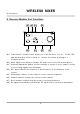
WIRELESS MIXER Operating Manual A. Receiver Module Part Functions A5 A6 A7 CHANNEL NOISE A8 RF SCAN ACT SENSITIVITY AF VOLUME A4 A3 A2 A1 (A1) Power Switch / Volume Control: Allows you to turn the mixer on & off. The AF LED light will flash when mixer is turned on. Increase the volume by turning in a clockwise direction. (A2) Audio Signal Level Indicator: Indicates the audio levels received from microphones.