MA-705 Instruction Manual ELECTRONICS CO., LTD.
Electronics Co., Ltd. Head office: 814, Pei-Kang Road, Chiayi, 600, Taiwan. Taipei office: 5, Lane 118, Sung-teh Road, Taipei, 110, Taiwan. Web-http: //www.mipro.com.tw E-mail: mipro@mipro.com.
WIRELESS AMPLIFIER Operating Manual Thank you for choosing a MIPRO MA-705 series Wireless Portable Public Address System. Please take time to read these instructions carefully so that you can achieve the best performance from the system. The MA-705 is a Wireless Portable Public Address System, housed in a heavy duty, ergonomically designed case. It offers 50 Watts (RMS) high fidelity output and may be optioned with a wired microphone, up to two wireless microphones, and a CD.
WIRELESS AMPLIFIER Operating Manual Back: 5 Anti-Shock CD Player 6 DC Power Switch B. Receiver Modules A. Control Panel (5) (6) (7) (8) (9) 7 Heat Sink 8 AC Input Socket 9 Battery Cover CD Player: Featuring an anti-shock mechanism. Please refer to the instruction manual for CD player that is included in the package. DC Power Switch: Turns DC power on/off of the unit. The indicator glows when you turn the power on.
WIRELESS AMPLIFIER Operating Manual A. Control Panel A9 A1 A2 A3 A4 A5 A6 A7 A8 (Fig.1) (A1) Tone Control : Turn counterclockwise to increase bass or turn clockwise to increase treble. Set at 12 o'clock for a flat response. (A2) Master Volume Control : Simultaneously adjusts the volume of all mixed audio inputs. (A3) LINE IN Volume Control: Controls the volume of the Line Socket (A6). (A4) Mic In Volume Control : Control the volume of the wired microphone (A7).
WIRELESS AMPLIFIER Operating Manual (B5) Scan Button: Press once to select receiving channel and autoscan the whole bandwidth to avoid interference channel. (B6) Channel Indicator: To display system's receiving channel. (B7) Noise Indicator: To display if the system is under interference. (B8) RF Signal Level Indicator: Indicate the RF signal strength received. C. SWITCHABLE CHANNELS FUNCTIONS 1. Functions: (a) This system incorporates advanced PLL synthesized oscillator design.
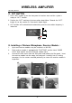
WIRELESS AMPLIFIER Operating Manual D. ACT BUTTON 1. Press "ACT" button (3) on the front panel of receiver once and the system is ready for "ACT" function. 2. Position the "ACT" marking of the transmitter about 30cm. Towards the "ACT" button (3) on the receiver as illustrated in below figure. 3. ACT function will be deactivated automatically once the transmitter frequency is locked on. ACT E. Installing a Wireless Microphone Receiver Module : 1. Up to two receiver modules may be installed in a MA-705.
WIRELESS AMPLIFIER Operating Manual 2. INSTALLING ACD PLAYER : A. Remove the cover plate (as shown in fig. 3-1) B. Connect the linking wire to the CD player's connecting socket (as shown in fig. 3-2) C. Gently push the CD player in to position and tighten accordingly (as shown in fig. 3-3) (fig. 3-1) (fig. 3-2) (fig. 3-3) 3. REPLACING BATTERIES A. Remove the screws and take off the battery cover (as shown in fig. 2-1) B. Gently remove the existing batteries (as shown in fig. 2-2) C.
WIRELESS AMPLIFIER Operating Manual 4. HELPFUL TIPS : 1. Please make sure the inbuilt rechargeable batteries are fully charged before and after use. A characteristic of rechargeable batteries is that they will selfdischarging gradually over a period of time. Therefore, if the system will not be used for a long period of time, please make sure the batteries are fully charged before storing the MA-705.
WIRELESS AMPLIFIER Operating Manual 5. SPECIFICATIONS : Specifications Item 1. Max. Power Output 50 Watts (RMS) in to a 8Ω Load 2. T. H. D. < 0.1 % 3. Frequency Response 50Hz ~ 18 Khz ± 3 dB 4. Speaker Built-in 8 Inch Full-range Speaker. 5. Receiver Module Up to 2 optional UHF or VHF receiver modules may be fitted to a MA-705. Please consult with your local supplier for frequencies 6.
HANDHELD WIRELESS MICROPHONE Operating Manual 1. PARTS NAMES AND FUNCTIONS 1 2 3 4 5 6 7 8 9 (Fig.1) 1. Grille: Protects cartridge, prevents "POP" noise and prevents microphone from rolling with polygonal shape. 2. Color Ring: For frequency differentiation. 3. Battery Status Indicator: Indicates power on / off and the battery status. When the power switch is turned ON, the red LEDs indicator flashes briefly, indicating normal battery status.
HANDHELD WIRELESS MICROPHONE Operating Manual 2. BATTERY INSERTION (Fig.2) 1. Unscrew battery cap in a counter-clockwise direction (7). 2. Insert a 9V battery into the battery compartment according to the correct polarity as shown in Fig.2. The moment the battery touches the terminals, the indicator will flash briefly (7). This means the polarity is correct. However, if no flash occurs, this indicates wrong insertion or that the battery is dead.
BODYPACK TRANSMITTER Operating Manual 1. PARTS NAMES AND FUNCTIONS 1 2 3 4 5 6 7 8 10 9 ACT (Fig. 1) 1. AF Input Jack: Connects to either lavaliere or headset microphone. (See 5 ways of connection on AF Input Connections) 2. Power Switch: Switch to ON position for operation. Switch to OFF position when not in use. 3. Battery Status Indicator: Indicates the power on / off and battery status. (a) When power switch is turned on: The LED indicator flashes briefly, indicating normal battery status.
BODYPACK TRANSMITTER Operating Manual 9. Battery Compartment and Cover: Accommodates one 9 Volt battery. 10.Detachable Belt Clip: Allows 360 degrees rotating to suit transmitting angles. To detach simply use a screwdriver at a 45 degree angle to unfasten. see diagram. 2. OPERATING INSTRUCTIONS 1. To adjust GT/MT Switch (8), and Gain Control (7), simply push down both snap locks on the sides of battery cover and flip it backwards to expose the adjustment panel. 2.
BODYPACK TRANSMITTER Operating Manual 3. AF 4-PIN INPUT CONNECTION METHOD (1) 2-Wire Electret Condenser Microphone Capsule PIN 1 SHIELD AUDIO 2 4 1 3 2 3 4 (2) 3-Wire Electret Condenser Microphone Capsule SHIELD PIN 1 2 AUDIO 4 1 3 BIAS 3 2 4 (3) Dynamic Microphone 2 1 SHIELD PIN 1 3 2 AUDIO 4 1 3 3 2 4 (4) Electric Guitar SHIELD PIN 1 2 AUDIO 4 3 1 2 3 4 (5) Line-in (Impedance 8KΩ ATT.
BODYPACK TRANSMITTER Operating Manual 4. BATTERY INSTALLATION 1. Pushing down both snap-locks on the sides of battery cover to open battery cover. (Fig. 3). 2. Insert a 9V battery into the battery compartment observing the correct polarity as shown in Fig. 4). Then push up to close the battery compartment as shown in Fig. 4). (Fig.3) (Fig.4) PS: When the microphone is not in use: Make sure the power to the microphone is switched off.