MIRA CODA THERMOSTATIC SHOWER VALVE Installation & User Guide These instructions are to be left with the user 1
PATENT APPLICATION GB 2 407 138A 2
SPECIFICATIONS Notes 1. The installation, commissioning and maintenance must be carried out in accordance with instructions supplied by the manufacturer, and be installed by qualified or competent persons. 2. Installations must comply with the requirements of UK Water Regulations/Byelaws (Scotland), Building Regulations or any particular regulations and practices, specified by the local water supplier. 3. The Mira Coda is supplied and designed to operate with Mira L11 shower fittings.
INSTALLATION General 1. The installation, commissioning and maintenance must be carried out according to instructions supplied, and must be conducted by qualified or competent person. 2. Before starting installation, ensure that all site requirements correspond to information given in the SPECIFICATION section. 3. DO NOT install product in a position where it could become frozen. 4. Install in a position with easy access for maintenance. 5. Accessible isolating valves MUST be provided for maintenance. 6.
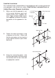
Solid Wall Installation For installation onto a stud partition or laminated panel wall, or onto unfixed rearentry pipework, refer to the next section: Stud Partition, Laminated Panel, or Unfixed Rear-entry Pipework Installation. 1. 1/2" BSP Female Connector Make sure that the pipework is set at the correct distance apart and solidly fixed as this supports the valve. Apply suitable thread sealant (not supplied) and attach the offset connectors to the pipework in the wall.
4. 5. 6. 7. Caution! Ensure supply pipework is flushed before installing the shower valve. Assemble the shower valve with a sealing washer in each inlet and attach to the offset connectors. Tighten the nuts using a suitable spanner. Connect the shower fittings to the shower valve outlet. Turn on the water supplies and check for leaks at all pipe connections. Sealing Washer Shower Valve Shower Valve Outlet Stud Partition, Laminated Panel, or Unfixed Rear-entry Pipework Installation 1.
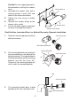
4. Apply suitable thread sealant (not supplied) and attach the offset connectors to the pipework in the wall. Make sure that the connectors are level and set at the correct distance apart. Mounting Bracket Offset Connector Pipework Wall Spanner Flats 5. 6. 7. Tighten the connection to the pipework while holding the offset connectors in place using a spanner on the spanner flats.
Caution! Ensure supply pipework is flushed before installing the shower valve. 8. Assemble the shower valve with a sealing washer in each inlet and attach to the offset connectors. 9. Tighten the nuts using a suitable spanner. 10. Connect the shower fittings to the shower valve outlet. 11. Turn on the water supplies and check for leaks at all pipe connections.
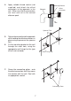
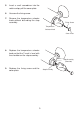
5. Insert a small screwdriver into the notch and pry off the cover plate. 6. Unscrew the fixing screw. 7. Remove the temperature selector knob without disturbing the stop assembly. Fixing Screw Temperature Selector Knob Cover Plate 8. Replace the temperature selector knob so that the 7 mark is level with the shoulder on the stop assembly . Stop Assembly (Shoulder) 9. Replace the fixing screw and the cover plate.
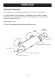
OPERATION Adjusting the Temperature The temperature is controlled by rotating the temperature selector knob. For safety reasons, the temperature is limited by a stop. To obtain a higher temperature, press the override button on the temperature selector knob and continue to rotate the knob. Adjusting the Flow The flow is controlled by rotating the flow selector knob.
FAULT DIAGNOSIS Read the section: Important Safety Information first. Provided that the Mira Coda has been correctly installed and is operated in accordance with the instructions contained in this guide, difficulties should not arise. If any maintenance is required then it must be carried out by a competent tradesperson for whom the fault diagnosis chart and maintenance instructions are provided. Before replacing any parts make sure that the underlying cause of the malfunction has been identified.
Symptom 6. Cause / Rectification Drip from handset. A small amount of water may be retained in the fitting after the shower control has been turned off. This may drain over a few minutes. This is quite normal. Changing the angle of the shower fitting may vary the draining time. Defective ceramic plates within the shower cartridge. Renew the cartridge assembly.
MAINTENANCE General This Product is precision engineered and should give continued safe and controlled performance, provided: 1. It is installed, commissioned, operated and maintained in accordance with manufacturers recommendations. 2. Periodic attention is given, when necessary, to maintain the product in good functional order. Lubricants Standard silicone-only based lubricants may be used to assist refitting. Warning! Use silicone-only based lubricants.
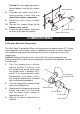
Maintaining the Non-Return Valves The non-return valves are located in the valve body, and are accessible through the inlet connectors. Caution! Ensure that the non-return valves are installed correctly to prevent crossflow or malfunction of the valve. 1. 2. 3. With the water supplies turned off and the thermostatic mixer removed, remove the washer, the circlip and the filter. Remove the non-return valve and clean any debris.
SPARES 456.29 Wall Mounting Bracket 1630.045 Temperature Knob Assembly 1630.041 Offset Connector Kit 1630.043 1630.042 Thermostatic Non Return Valve Cartridge 1630.049 Filter Washer 1630.044 Temperature Stop 1630.047 Flow Knob Assembly 1630.048 Outlet Connector 1630.
CUSTOMER SERVICE UKAS 1065367-W2-A 16 © Kohler Mira Limited, August 2006