Mira Escape Thermostatic 9.0, 9.
INTRODUCTION Thank you for purchasing a quality Mira product. To enjoy the full potential of your new product, please take time to read this guide thoroughly. Having done so, keep it handy for future reference. The Mira Escape Thermostatic is an electric shower with separate controls for power selection and temperature/flow adjustment. A unique thermostatic valve stabilises temperature changes caused by water pressure fluctuations. These can result from taps being turned on or off, or toilets being flushed.
IMPORTANT SAFETY INFORMATION WARNING - This shower can deliver scalding temperatures if not operated, installed or maintained in accordance with the instructions, warnings and cautions contained in this guide and on or inside the appliance. TO REDUCE THE RISK OF FIRE, ELECTRIC SHOCK OR INJURY: 1. Installation of this shower must be carried out in accordance with these instructions by qualified, competent personnel. 2. Isolate the electrical and water supplies before commencing installation.
PACK CONTENTS Tick the appropriate boxes to familiarize yourself with the part names and to confirm that the parts are included.
WIRING DIAGRAM Thermal Cutout Dual Disc L BROWN RED BROWN BROWN Power On Neon Solenoid Valve BROWN Pressure/Power Selector Switch BROWN RED BLACK BLACK Low Flow Neon BLUE BLACK START/STOP E BROWN BLUE N GREEN Tank Connection GREEN Load Inlet Connector Internal Wiring Diagram 5 RED
SPECIFICATIONS European Conformity Information The Mira Escape range of showers comply with the following European directives: 2006/95/EC Low Voltage Directive, 2004/108/EC EMC Directive. The Mira Escape range of showers are high power appliances and are subject to conditional connection. If the main electrical supply fuse is rated less than 80 Amps, the local electricity supply company must be contacted to confirm if the electrical supply is adequate.
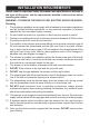
INSTALLATION REQUIREMENTS Please read the Important Safety Information and specifications sections at the front of this guide, and the requirements detailed in this section before installing the shower. WARNING - TO REDUCE THE RISK OF FIRE, ELECTRIC SHOCK OR INJURY: Plumbing 1. The plumbing installation must comply with all national or local water regulations and all relevant building regulations, or any particular regulation or practice specified by the local water supply company. 2.
15. A full bore/non restrictive servicing valve must be fitted in a readily accessible position adjacent to the shower to facilitate maintenance of the shower. DO NOT use a valve with a loose washer plate (jumper) as this can lead to a build up of static pressure. 16. A water treatment device should be installed where the water hardness may exceed 200 ppm. Malfunctions caused by excessive limescale formation are not covered by this shower’s guarantee (see back page for details). 17.
WARNING - TO REDUCE THE RISK OF FIRE, ELECTRIC SHOCK OR INJURY: Electrical 1. The electrical installation must comply with BS 7671 (commonly referred to as the IEE Wiring Regulations) and all relevant building regulations, or any particular regulation or practice specified by the local electricity supply company. 2.
INSTALLATION Installation of Mira Escape Warning! Turn off the electrical and water supplies before proceeding with the installation of the Mira Escape. The electricity must be turned off at the mains and the appropriate circuit fuse removed, if applicable. Note! An installation template is supplied to help you install the Mira Escape. Wall fixings are not supplied. For solid wall structures a red rawl plug and a no. 8 x 1½” countersunk brass or stainless steel screw should be used.
Three case inserts are supplied with the Mira Escape, so that they can be trimmed to suit the supplies entering the product. Before fitting the cover, make sure that the case inserts are fitted. Thoroughly flush the mains-fed cold water supply pipe. The supply must be clean and free from debris BEFORE connecting the Mira Escape. To flush the pipework, turn on the water supply and drain a minimum of 10 litres (2 gallons) of water into a bucket or catchment area. Turn off the water supply.
L = BROWN E = GREEN/YELLOW Firmly connect the conductors. Do not exert strain on the terminal block. N = BLUE Cover Retaining Screw Refit the Service Tunnel and Cover. Make sure they fit correctly. Do not overtighten screws. Do not use alternative screws to secure the Cover. This can cause internal damage to the appliance. Do not seal around the back of appliance.
Holes For Cover Retaining Screws Case Insert Fixing Screw Terminal Block Heater Tank Electrical Supply Cable Inlet Connector Assembly Cold Water Supply Pipe (Bottom Entry) Service Tunnel 13
COMMISSIONING Before carrying out the commissioning procedure install the Shower Fittings, refer to the Shower Fittings Installation and User Guide. If you are unsure how an electric shower works, please read through the section “User Instructions” before continuing. 1. 2. 3. Electrical supply is turned off at the mains. 4. Turn control to full cold. Turn the water supply fully on. Check for water leaks. Set control to ‘I’. 7. 8. 5. 6. Switch on electrical supply. 9.
10. 11. 12. + _ 0 - 10 Secs Turn control to full cold. Set control to ‘II’. 13. 14. The temperature will rise slightly. + _ 5 - 10 Secs Set control to ‘III’. The temperature will rise further. 15. 16. Adjust temperature as required. Flow rate will adjust automatically. 17. Press STOP button, light on the button goes out. Shower flow will continue for a few seconds before stopping. Isolate power. 18. 0 - 5 Secs The shower will purge water from its tank for a few seconds.
USER INSTRUCTIONS How Your Electric Shower Works Heated water is produced by adjusting the flow of cold water passed through a heater tank. + LD CO _ The shower has three heater settings. + _ + _ The warmer the shower, the lower the flow rate and vice versa.
Thermostatic (Temperature-Stable) The shower's top priority is to keep the desired water temperature constant. Electric showers with thermostatic control are able to keep a stable temperature across the range from hot to cold, whilst also dealing with fluctuations in electrical and water supplies. As a result, there is a temperature limit the shower cannot go beyond. For safety, this temperature is factory set and cannot be adjusted to make the shower hotter or colder.
USER SAFETY INFORMATION WARNING - THIS SHOWER CAN DELIVER SCALDING TEMPERATURES IF NOT OPERATED, INSTALLED OR MAINTAINED IN ACCORDANCE WITH THE INSTRUCTIONS, WARNINGS AND CAUTIONS CONTAINED IN THIS GUIDE AND ON OR INSIDE THE APPLIANCE. To reduce the risk of fire, electric shock or injury: 1. Make sure that you fully understand how to operate this shower before use, read all operating instructions and retain this guide for future reference. 2.
Using your Shower Read the section “User Safety Information” first. 1. 2. Switch on electrical supply. 3. Press the ‘Start/Stop’ button, light on the button comes on. 4. + _ Set to desired position. 5. Check water temperature before entering shower. + _ Allow 10 - 15 seconds for any temperature adjustments to reach the handset. 6. 7. Press STOP button, light on the button goes out. Shower flow will continue for a few seconds before stopping. Isolate power. Residual water may drain over a few minutes.
The Effect of Seasonal Changes + _ For a cold shower select I. For a summer warm shower select II. For a winter warm shower select III. During extremes of mains water supply temperature, adjust heater setting to obtain a better showering temperature. The Effect of Other Water Devices Example of how shower temperature stabilises due to pressure changes. + _ ± 2°C Water inlet pressure fluctuations due to other draw offs (e.g. flushing toilet).
FAULT DIAGNOSIS The trouble shooting information tabled below gives details on probable causes and remedies should difficulties be encountered whilst the shower is in operation. Warning! There are no user serviceable components beneath the cover of the appliance.
Symptom (continued) Unable to select a hot enough shower (cold only) Power Light ON Low Flow Light ON Heater Setting I / II / III OFF ANY Check hose and replace if necessary, see section - 'USER MAINTENANCE'. Restriction in Showerhead mode Select different Showerhead mode Insufficient water supply T h e m i n i m u m s t a t i c pressure for shut off. pressure to ensure shut off and prevent dripping is 0.2 bar. Note! If other appliances are operating, static pressure may drop below 0.2 bar.
Symptom Operation of temperature control has little or no effect on water temperature. No change in temperature between I/II/III settings. Water will not turn off. Appliance fails to produce hot water when set on II/III heater settings. Power Light Low Flow Light Heater Setting I / II / III ON ON II / III OFF Probable Cause Possible Remedy Showerhead or inlet filter blocked. Remove and clean. Inlet valve faulty. Replace. Heater tank failure. Replace. Microswitch failure. Replace.
USER MAINTENANCE WARNING - TO REDUCE THE RISK OF FIRE, ELECTRIC SHOCK OR INJURY: DO NOT use the showerhead to clean the shower. There are no user serviceable parts inside the shower. Only qualified, competent personnel should remove the front cover, mains connections are exposed when the cover is removed. If the shower is not to be used for a long period, the electrical supply and water supply to the shower should be isolated.
SERVICING WARNING There are no user serviceable parts inside the shower. Servicing of the shower must only be carried out by qualified, competent personnel following the instructions provided in this guide and those provided with any spare part. Before replacing any parts, ensure that the underlying cause of the malfunction has been resolved.
SPARE PARTS A A 1563.519 Terminal Block 1563.719 Thermal Switch 1563.539 Switching Assembly 872.01 Microswitch (2 Pin) 1563.532 (9.0kW) 1563.533 (9.8kW) Heater Tank 1563.540 Inlet Valve 1563.538 Cam and Pulley 872.28 Microswitch (3 Pin) B, C, D A 405.58 Inlet Connector 1563.537 Control Belt A 406.27 Inlet Filter A 416.38 Inlet Clamp 416.51 Coil 416.48 Latching Switch A 1563.534 Outlet Connector A B, C 1563.694 Neon Assembly 1563.547 (Satin) 1563.548 (Chrome) 1563.
ACCESSORIES Genuine Mira accessories can be purchased direct from Customers Services (our contact details can be found on the back cover of this guide) or from approved stockists or merchants. Everclear Showerhead White - 2.1616.030 Chrome - 2.1616.031 Mira's new Everclear range has been specially designed for hard water areas and reduces the risk of lime scale build up. Note! Only suitable for Electric showers rated at 9kW and higher. Logic Showerhead Holder White - 2.1605.149 White/Chrome - 2.1605.
CUSTOMER SERVICE Guarantee Your product has the benefit of our manufacturer’s guarantee which starts from the date of purchase. To activate this guarantee, please return your completed registration card, visit our website or free phone 0800 0731248 within 30 days of purchase (UK only). Within the guarantee period we will resolve defects in materials or workmanship, free of charge, by repairing or replacing parts or product as we may choose.