MIRA ESCAPE THERMOSTATIC ELECTRIC SHOWER Installation and User Guide These instructions are to be left with the user 1
Contents Introduction.............................................................................................. 3 Guarantee.................................................................................................. 4 Patents and Design Registration........................................................... 4 Important Safety Information.................................................................. 5 Pack Contents Checklist.......................................................................
Introduction Thank you for purchasing a quality Mira product. To enjoy the full potential of your new product, please take time to read this guide thoroughly. Having done so, keep it handy for future reference. The Mira Escape Thermostatic is an electric shower with separate controls for power selection and temperature/flow adjustment. A unique thermostatic valve stabilises temperature changes caused by water pressure fluctuations. These can result from taps being turned on or off, or toilets being flushed.
Recommended Usage Domestic ü Light Commercial ü Heavy Commercial û Healthcare û Guarantee For domestic installations, Mira Showers guarantee the Mira Escape 9.0 kW and 9.8kW against any defect in materials or workmanship for a period of two years from the date of purchase (shower fittings for one year). For non-domestic installations, Mira Showers guarantee the Mira Escape 9.0 kW and 9.8kW against any defect in materials or workmanship for a period of one year from the date of purchase.
Important Safety Information WARNING TO REDUCE THE RISK OF FIRE, ELECTRIC SHOCK OR INJURY: 1. Installation of this shower must be carried out in accordance with these instructions, and must be conducted by competent personnel. 2. Isolate the electrical and water supplies before commencing installation. The electricity must be switched off at the consumer unit and the appropriate circuit fuse removed, if applicable. 3.
16. Electric showers can deliver scalding temperatures if not operated, installed or maintained in accordance with the instructions, warnings and cautions contained in this guide and on or inside the shower. 17. Rapid or excessive operation of the shower controls may result in high or unstable outlet water temperatures. Operate controls gradually and allow 10-15 seconds to stabilise checking the temperature before entering the shower. 18.
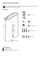
Pack Contents Checklist Tick the appropriate boxes to familiarize yourself with the part names and to confirm that the parts are included.
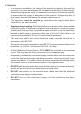
Specifications 1. Plumbing • Minimum maintained inlet pressure for 9.0 kW and 9.8 kW 70 kPa (0.7 bar). • 100 kPa (1.0 bar) recommended for satisfactory operation. • Maximum static inlet pressure 1000 kPa (10 bar). • Minimum static pressure 20 kPa (0.2 bar) to keep the inlet valve closed. 2. Electrical • The Mira Escape 9.0 kW requires a 40 Amp fuse. The Mira Escape 9.8kW requires a 45 Amp fuse. • The terminal block will accept cable up to 16 mm².
• Avoid layouts where the shower hose will be sharply kinked. This may reduce the life of the hose. • A Soap Dish/Hose Retaining Ring is supplied to prevent the handset from dropping below the spill-over level of the bath or shower tray, which could lead to contamination from back-siphoning. The supplied Hose Retaining Ring should meet the majority of user requirements for shower installations with flexible outlet fittings. However, there will be occasions when it will not provide a suitable solution.
2. Electrical • In a domestic installation, the rating of the electricity supplier’s fuse and the consumer unit must be adequate for the additional demand. All Mira electric showers are high power units, it is essential to contact your electricity supplier to ensure that the supply is adequate for the product. Voltage drop due to local heavy demand will reduce the shower’s performance. • The appliance must be earthed by connecting the supply-cable earth conductor to the earth terminal.
Consumer Unit Double-pole Isolating Switch Installation Installation of Mira Escape Warning! Turn off the electrical and water supplies before proceeding with the installation of the Mira Escape. The electricity must be turned off at the mains and the appropriate circuit fuse removed, if applicable. Note! An installation template is supplied to help you install the Mira Escape. Cover Retaining Screw Remove the three cover retaining screws, the cover and the service tunnel.
Determine the direction of the inlet water supply: top (falling), bottom (rising), or back inlet . Note! Make sure that the back inlet does not go directly back into the wall. Use a soldered elbow. Swivel the inlet connector assembly to suit. Remove the inlet blanking cap. Avoid trapping the green earth bonding wire. Three case inserts are supplied with the Mira Escape, so that they can be trimmed to suit the supplies entering the product.
Feed cable into Case. Fit Earth sleeve (not supplied) and strip insulation. Do not twist cable cores. Important! Make sure that the inlet earth wire is routed as shown. Failure to do so may cause product malfunction. L = BROWN E = GREEN/YELLOW Firmly connect the conductors. Do not exert strain on the terminal block. N = BLUE Cover Retaining Screw Refit the Service Tunnel and Cover. Make sure they fit correctly. Do not overtighten screws. Do not use alternative screws to secure the Cover.
Holes For Cover Retaining Screws Case Insert Fixing Screw Terminal Block Heater Tank Electrical Supply Cable Inlet Connector Assembly Cold Water Supply Pipe (Bottom Entry) Service Tunnel 14
Commissioning Before carrying out the commissioning procedure install the Shower Fittings, refer to the Shower Fittings Installation and User Guide. If you are unsure how an electric shower works, please read through the section “User Instructions” before continuing. 1. 2. 3. Electrical supply is turned off at the mains. 4. Turn control to full cold. Turn the water supply fully on. Check for water leaks. Set control to ‘I’. 7. 8. 5. 6. Switch on electrical supply. 9.
10. 11. 12. + _ 0 - 10 Secs Turn control to full cold. Set control to ‘II’. 13. 14. The temperature will rise slightly. + _ 5 - 10 Secs Set control to ‘III’. The temperature will rise further. 15. 16. Adjust temperature as required. Flow rate will adjust automatically. 17. Press STOP button, light on the button goes out. Shower flow will continue for a few seconds before stopping. Isolate power. 18. 0 - 5 Secs The shower will purge water from its tank for a few seconds.
User Instructions How Your Electric Shower Works Heated water is produced by adjusting the flow of cold water passed through a heater tank. + LD CO _ The shower has three heater settings. + _ + _ The warmer the shower, the lower the flow rate and vice versa.
Thermostatic (Temperature-Stable) The shower's top priority is to keep the desired water temperature constant. Electric showers with thermostatic control are able to keep a stable temperature across the range from hot to cold, whilst also dealing with fluctuations in electrical and water supplies. As a result, there is a temperature limit the shower cannot go beyond. For safety, this temperature is factory set and cannot be adjusted to make the shower hotter or colder.
Using your Shower Read the section “Important Safety Information” first. 1. 2. Switch on electrical supply. 3. Press the ‘Start/Stop’ button, light on the button comes on. 4. + _ Set to desired position. 5. Check water temperature before entering shower. + _ Allow 10 - 15 seconds for any temperature adjustments to reach the handset. 6. 7. Press STOP button, light on the button goes out. Shower flow will continue for a few seconds before stopping. Isolate power.
The Effect of Seasonal Changes + _ For a cold shower select I. For a summer warm shower select II. For a winter warm shower select III. During extremes of mains water supply temperature, adjust heater setting to obtain a better showering temperature. The Effect of Other Water Devices Example of how shower temperature stabilises due to pressure changes. + _ ± 2°C Water inlet pressure fluctuations due to other draw offs (e.g. flushing toilet).
Fault Diagnosis The trouble shooting information tabled below gives details on probable causes and remedies should difficulties be encountered whilst the shower is in operation. Warning! There are no user serviceable components beneath the cover of the appliance. Only a competent tradesperson should remove the front cover! Symptom Power Light Low Flow Light Heater Setting I/II/III Appliance Fails to operate OFF OFF Any Electrical supply isolated Switch on electrical supply at double pole switch.
Symptom Power Light Low Flow Light Heater Setting I/II/III Probable Cause Possible Remedy Low or no flow. ON ON Any Water supply pipework or inlet filter restricted by a blockage or partial blockage. Water supply pipework or inlet filter restricted by a blockage or partial blockage. ON ON Any I n s u f f i c i e n t w a t e r Contact local water supply pressure/flow for company. Supply pressure operation. must be a minimum of 0.7 bar.
Symptom Power Light Low Flow Light Heater Setting I/II/III Water will not turn off. ON OFF Any Inlet valve, solenoid, or Replace as necessary. start/stop switch faulty. ON ON Any Supply pressure below 0.2 bar. Contact local water company. Check mains water static pressure. ON ON II/III Insufficient water supply. Contact local water company. ON OFF II/III Possible failure of the Check the continuity of microswitch or thermal the microswitch or heater switch.
Maintenance Handset - Cleaning Clean with mild washing up detergent or soap solution. Wipe dry with a soft cloth. Poor shower performance can be avoided by cleaning the spray plate. Use thumb or soft cloth to wipe rubber nozzles. The handset must also be descaled regularly. Inlet Filter - Cleaning/Renewing Read the section “Important Safety Information” first Make sure that the electrical supply is turned off at the mains and that the water supply is fully turned off.
Hold a wrench across the flats of the metal connector. Unscrew the filter using another wrench as shown. Clean or renew the Filter as necessary. Refit in reverse order making sure the Filter is screwed fully home. Do not overtighten. Make sure plumbing connections are sealed before restoring electricity supply. Refit the Service Tunnel and Cover. Make sure they fit correctly. Do not overtighten screws.
Dimensions 90 mm 79 mm 207 mm 340 mm 348 mm 26
Wiring Diagram Thermal Cutout Dual Disc L BROWN RED BROWN BROWN Power On Neon Solenoid Valve BROWN Pressure/Power Selector Switch BROWN RED BLACK BLACK Low Flow Neon BLUE BLACK START/STOP E BROWN BLUE N GREEN GREEN Load Tank Connection Inlet Connector Internal Wiring Diagram 27 RED
Spare Parts Mira Escape 405.58 406.27 416.38 416.48 416.51 872.01 872.28 1563.519 1563.522 1563.532 1563.533 1563.534 1563.537 1563.538 1563.539 1563.540 1563.541 1563.544 1563.545 1563.547 1563.548 1563.550 1563.551 1563.694 1563.719 Inlet Connector Assembly Inlet Filter (with ‘O’ seal fitted) Clamp Bracket (Inlet) Latching Switch Solenoid Coil Microswitch N/O - 2 pin Microswitch C/O - 3 pin Terminal Block Assembly Cover Seal (not shown) Thermostatic Valve/Heater Tank 9.
B C A A A 1563.719 C C 1563.519 1563.539 872.01 1563.532 1563.533 C 1563.694 A 1563.538 A A 872.28 1563.694 1563.540 406.27 416.51 416.48 1563.507 B 405.58 A A C A 416.38 1563.534 1563.537 A 1563.544 1563.
Accessories Genuine Mira accessories can be purchased direct from Customers Services (our contact details can be found on the back cover of this guide) or from approved stockists or merchants. Everclear Showerhead White - 2.1616.030 Chrome - 2.1616.031 Mira's new Everclear range has been specially designed for hard water areas and reduces the risk of lime scale build up. Logic Showerhead Holder White - 2.1605.149 White/Chrome - 2.1605.150 An alternative to the traditional slide bar.
Notes 31
Customer Service Guarantee Your product has the benefit of our manufacturer’s guarantee which starts from the date of purchase. To activate this guarantee, please return your completed registration card, visit our website or free phone 0800 0731248 within 30 days of purchase (UK only). Within the guarantee period we will resolve defects in materials or workmanship, free of charge, by repairing or replacing parts or product as we may choose.