Mira Moto, mira pace, Mira Minilite & Mira Miniduo Thermostatic Mixers Installation & User Guide These instructions must be left with the user.
Contents Introduction Introduction 2 Patents 2 Safety Warnings 3 Pack Contents 4 Specifications 5 Pressures 5 Temperatures 5 Thermostatic Shut-down 5 Connections 5 Dimensions 6 Installation Thank you for purchasing a quality Mira product. To enjoy the full potential of your new product, please take time to read this guide thoroughly, having done so, keep it handy for future reference.
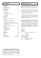
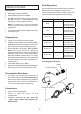
Pack Contents Tick the appropriate boxes to familiarise yourself with the part names and to confirm that all of the parts are included. Mira Minilite EV Mira Moto EV Mira Miniduo EV Mira Pace EV q 2 x Concealing Plates q 2 x Compression Nuts q 2 x Olives q 2 x Wall plugs q 2 x Fixing Screws q 1 x 2.
Safety Warnings Mira thermostatic mixers are precision engineered and should give continued safe and controlled performance, provided: 1. They are installed, commissioned, operated and maintained in accordance with manufacturers recommendations. 2. Periodic attention is given, when necessary, to maintain the product in good functional order. Caution! 1. Read all of these instructions. 2. Retain this guide for later use. 3. Pass on this guide in the event of change of ownership of the installation site. 4.
Flow Regulators Specifications Site conditions and thermostatic mixer model will determine the flow regulator requirements. For gravity systems (0.5 bar or below) remove the inlet and outlet flow regulators (where fitted). Pressures • • • • Max Static Pressure: 10 Bar. Max Maintained Pressure: 5 Bar. Min Maintained Pressure (Gravity System): 0.1 Bar. (0.1 bar = 1 Metre head from cold tank base to shower handset outlet). Model Note! For gravity fed / other low pressure systems (0.
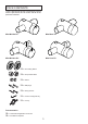
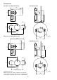
Dimensions Mira Moto and Mira Minilite EV Mira Minilite BIV 113 Ø54 20 17 21 39 56-76 39-59 76.5 Ø46 110 See Note! below Ø183 Mira Pace and Mira Miniduo EV 103 125 Mira Miniduo BIV Ø54 20 17 21 39 56-76 53-73 95 Ø46 All dimensions in mm 110 See Note! below Ø183 Note! If replacing an existing installation with pipework centres between 133 mm and 153 mm a universal retrofit accessory kit is available, refer to section: ‘Accessories’.
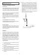
6. Decide on a suitable position for the Mixer. The position of the Mixer and the Shower Fittings must provide a minimum gap of 25 mm between the spill-over level of the shower tray/bath and the handset (refer to illustration). This is to prevent back-siphonage. For further information on the installation of your Shower Fittings, refer to the Fittings Installation and User Guide. Note! Only use Shower Fittings recommended by the manufacturer or supplier.
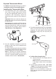
Exposed Thermostatic Mixers For Built-in Thermostatic Mixers go to section: ‘Installation, Built-in Thermostatic Mixers’. Installing the Thermostatic Mixer 1. The thermostatic mixer can be installed with rear, rising or falling supply inlets. Decide on the most appropriate method for your installation, and if necessary, loosen the grubscrews and rotate the inlet elbows to suit. Important! Make sure that the elbows are pushed fully onto the mixer before tightening the grubscrews.
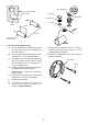
Flow Regulator 23 mm from finished wall surface Plug Cap Sealing Plug COLD Elbow Outlet Nipple ‘O’ Seal 23 mm HOT 110 mm Recess Ø19 mm x 2 mm deep 6. Reverse Inlet Supplies Only: a) Using a suitable tool, carefully remove the plug cap from the centre of sealing plug to reveal keyway. b) Remove the sealing plug using the ‘O’ key (supplied) or a 12 mm hexagonal key.
9. For Rear Entry Supplies Only: a) Fit the concealing plates over the inlet pipes. Note! Apply silicone sealant to the back face of the flange. 15.Fit the shower fittings, refer to your shower fittings installation and user guide for instructions. Important! A 12 litre/minute flow regulator is fitted inside the outlet nipple. This can be removed for gravity fed / other low pressure systems (0.5 bar or below), refer to section: ‘Specifications, Flow Regulators’. 16.
Installing the Built-in Thermostatic Mixer 4. Determine the route for the hot and cold supply pipework and for the outlet pipework. When connecting to the BIV shower fittings it is recommended that the outlet be positioned to one side of the mixer. This is to prevent the flexible hose from obstructing the shower controls (refer to illustration). 1. Carefully remove the concealing cap from the control knob. 2. Unscrew the grubscrew using a 2.5 mm hexagonal key (supplied) and pull off the control knob(s).
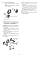
6. Reverse Inlet Supplies Only: a) Remove the sealing plug using the ‘O’ key (supplied) or a 12 mm hexagonal key. b) Remove the outlet nipple using the ‘O’ key (supplied) or a 12 mm hexagonal key. c) Refit the sealing plug and outlet nipple in the opposite outlets and tighten. Note! Make sure that the ‘O’ seals are correctly fitted. d) Rotate the mixer 180°. e) If necessary, loosen the grubscrew on each elbow using the 2.5 mm hexagon key (supplied). Remove the elbows and install on opposite sides.
12.Insert the wall plugs (supplied) and attach the mixer to the wall or timber noggin with the screws provided. 13.Fit the compression nuts and olives onto the pipework, connect the pipes and tighten the compression nuts. Important! Make sure that the outlet pipework protrudes through the wall by approximately 30 mm and temporarily cap off. Important! For stud partition/laminated panel installations fit the wallplate over the outlet pipework on the inside of the panel.
20.Remove the assembly from the wall and separate the backplate from the wallplate. 21.For solid walls drill two 6 mm holes for the wall plugs. For other types of wall structure alternative fixings may be required (not supplied). If necessary, make a recess 6 mm deep to accept the wallplate for flush fitting of the outlet to the wall surface. Caution! Make sure that you do not drill into pipework in the wall. 22.
Concealing Ring Screws Apply Silicone Sealant 32.Fit the concealing plate to the concealing ring. 33.Refit the control knobs. 34 Fit the shower fittings, refer to your shower fittings installation and user guide for instructions. Important! Make sure that the 12 litre/minute flow regulator (supplied) is fitted under the hose washer (refer to illustration). Note! This can be left out for gravity fed / other low pressure systems (0.5 bar or below). Hose Washer Flow Regulator 35.
6. Rotate the hexagon key until the required maximum temperature is obtained at the shower. Anticlockwise to increase the temperature, or clockwise to decrease the temperature (¼ turn = approximately 1°C). 7. Once the desired maximum blend temperature has been achieved turn off the mixer by rotating either the hub or flow control lever (depending on model) fully clockwise. Note! Do not remove the hub. 8. If applicable refit the hub retaining screw. 9.
Operation The Mira Moto and Mira Minilite thermostatic mixers have a single sequential control lever for on/off and temperature control. The control lever operates anti-clockwise in the following sequence: • • • • • Off On Cold Warm Maximum Preset Temperature Off Maximum Preset Temperature The Mira Pace and Mira Miniduo thermostatic mixers have separate control levers for on/off and temperature.
Lubricants User Maintenance Silicone based lubricants must only be used on the rubber seals. Caution! Oil based or other lubricant types may cause rapid deterioration of seals. If you require a Mira trained service engineer or agent, refer to section: ‘Customer Services’. Fault Diagnosis Cleaning Symptom: Only hot or cold water from the mixer outlet. • • The chrome plated parts should be cleaned using a mild washing up detergent or soap solution, rinsed and then wiped dry with a soft cloth.
Notes 19
Notes 20
Notes 21
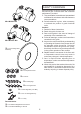
Spare Parts B Exposed Models 1663.157 Backplate Assembly A B 1663.156 Pipe Concealing Plates (x2) C B,C 1663.153 Elbow Assembly 1663.154 Elbow Connector Assembly A 1663.152 Thermostatic Cartridge Assembly A C 1663.155 Filter Pack (x2) C 1663.160 Outlet Plug 1663.213 Flow Regulator C A 1663.158 Outlet Nipple 1663.151 Hub and Bearing Assembly 1663.156 Control Lever Assembly (Minilite) Mira Minilite and Mira Moto Models Only 1663.150 Control Lever Assembly (Moto) C C 1663.
Built-in Models 1663.154 Elbow Connector Assembly 1663.187 Backplate Assembly 1663.188 Elbow Assembly D 1663.158 Outlet Nipple B C, D C A C D 1663.152 Thermostatic Cartridge Assembly A C A D C 1663.160 Outlet Plug 1663.151 Hub and Bearing Assembly 1663.155 Filter Pack (x2) 1663.156 Control Lever Assembly (Minilite) 1663.186 Concealing Plate Assembly C 1663.166 Thermostatic Cartridge Assembly A C 1663.165 Hub and Retainer Assembly 1663.163 Control Lever Assembly (Miniduo) 1663.
Customer Service Guarantee of Quality Mira Showers guarantee your product against any defect in materials or workmanship for the period shown in the Guarantee Registration Document included with your shower. Alternatively, to confirm the applicable guarantee period please contact Customer Services. To validate the guarantee, please return your completed registration card. Within the guarantee period we will resolve defects, free of charge, by repairing or replacing parts or modules as we may choose.