MIRA MOTO, MIRA PACE†, MIRA MINILITE†, AND MIRA MINIDUO† (†including Eco models) THERMOSTATIC MIXERS INSTALLATION & USER GUIDE These instructions must be left with the user.
CONTENTS INTRODUCTION Introduction 2 Guarantee 3 Recommended Usage 3 Patents and Design Registration 3 Safety Warnings 3 Pack Contents 4 Exposed Thermostatic Mixers 4 Built-in Thermostatic Mixers 5 Valve Combinations 6 Specifications 7 Installation 9 Suitable Plumbing Systems 9 General 9 Exposed Thermostatic Mixers Adjustable Elbow Installation The Mira Pace, Mira Pace with Eco Showerhead, Mira Miniduo and Mira Miniduo with Eco Showerhead are thermostatic mixers with separate on
Guarantee SAFETY WARNINGS For domestic installations, Mira Showers guarantee the products listed in this guide against any defect in materials or workmanship for a period of three years from the date of purchase (shower fittings for one year). For non-domestic installations, Mira Showers guarantee the products listed in this guide against any defect in materials or workmanship for a period of one year from the date of purchase.
Documentation PACK CONTENTS q 1 x Guarantee Registration Document q 1 x Installation Template Tick the appropriate boxes to familiarise yourself with the part names and to confirm that all of the parts are included. Exposed Thermostatic Mixers Component Pack q 1 x Thermostatic Mixing Valve q 2 x Concealing Plates q 2 x Compression Nuts q 2 x Olives Mira Minilite EV or Mira Minilite Eco EV q 2 x Wall Plugs q 2 x Fixing Screws q 1 x 2.
Built-in Thermostatic Mixers Documentation q 1 x Guarantee Registration Document q 1 x Cardboard Building-in Shroud q 1 x Thermostatic Mixing Valve Component Pack q 3 x Compression Nuts q 3 x Olives Mira Minilite BIV or Mira Minilite Eco BIV q 5 x Wall Plugs q 5 x Fixing Screws q 1 x 2.
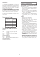
Valve Combinations These thermostatic mixers are available with various shower fittings and water saving features, refer to the table below to identify your mixer valve combination: Mixer Valve Shower Fittings Flow Regulator Flow Rate Colour Comments Moto EV / Minilite EV L14A 12 L/Min Red Supplied in the component pack, designed to be fitted in the shower valve outlet Pace EV / Miniduo EV L98B 12 L/Min Red Supplied in the component pack, designed to be fitted in the shower valve outlet Minil
Flow Rates SPECIFICATIONS Typical Flow Rates. For Type 2 Valves, the supply conditions specified in section: ‘Type 2 Valves - Application’ take precedence over the operating parameters which follow. Mira Miniduo with Mira L98B Shower Fittings: • • • • Flow Rate (L/Min) Pressures Max Static Pressure: 10 Bar. Max Maintained Pressure: 5 Bar. Min Maintained Pressure (Gravity System): 0.1 Bar (0.5 Bar for models with Eco Showerhead). (0.1 bar = 1 Metre head from cold tank base to showerhead outlet).
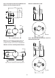
Minilite and Minilite Eco BIV Pace, Pace with Eco Showerhead, Miniduo and Miniduo with Eco Showerhead EV 20 Ø54 125 21 56-76 17 39-59 39 95 Ø46 Ø183 103 110 Pace, Miniduo BIV and Miniduo with Eco Showerhead BIV / BIR See Note! below Note! If you are retro-fitting your mixing valve onto existing pipework, an Adjustable Elbow Pack is available if required, refer to section: ‘Accessories’. 20 Miniduo and Pace with Adjustable Elbows 76.
3. Isolating valves must be installed close to the Mixer for ease of maintenance. 4. Pipework must be rigidly supported and avoid any strain on the connections. 5. Pipework dead-legs should be kept to a minimum. 6. Decide on a suitable position for the Mixer. The position of the Mixer and the Shower Fittings must provide a minimum gap of 25 mm between the spill-over level of the shower tray/ bath and the showerhead (refer to illustration). This is to prevent back-siphonage.
Exposed Thermostatic Mixers 3. For solid walls drill the holes for the backplate with a 6 mm drill and insert the wall plugs (supplied). For other types of wall structure alternative fixings may be required (not supplied). For Built-in Thermostatic Mixers go to section: ‘Installation, Built-in Thermostatic Mixers’. 1. The thermostatic mixer can be installed with rear, rising or falling supply inlets.
6. Reversed Inlet Supplies Only: a) Using a suitable tool, carefully remove the plug cap from the centre of sealing plug to reveal keyway. b) Remove the sealing plug using the ‘O’ key (supplied) or a 12 mm hexagonal key. c) Unscrew the outlet nipple using the ‘O’ key (supplied) or a 12 mm hexagonal key. Note! On Mira Minilite Eco models carefully remove the flow regulator from the outlet nipple first. d) Refit the sealing plug and outlet nipple in the opposite outlets and tighten.
9. For Rear Entry Supplies Only: a) Fit the concealing plates over the inlet pipes. Note! Apply silicone sealant to the back face of the flange. 15.Fit the shower fittings, refer to your shower fittings installation and user guide for instructions. Important! For high pressure systems (above 0.5 bar) make sure that the flow regulator (supplied) is fitted, refer to section: ‘Flow Regulators’. 16.Turn on the hot and cold water supplies and check for leaks. 17.
Adjustable Elbow Installation Adjustable Backplate 1. Unscrew the elbow grubscrews on the thermostatic mixer with a 2.5 mm hexagonal key (supplied with the thermostatic mixer), pull off the inlet elbows and discard. 2. Using the ‘O’ key (supplied with the thermostatic mixer) or a 12 mm hexagonal key, unscrew the inlet nipples and discard. 3. Fit the new adjustable elbow inlet nipples and tighten with the ‘O’ key. 4. Make sure that the ‘O’ seal is fitted and push the new elbow fully onto the inlet nipple.
Built-in Thermostatic Mixers 4. Determine the route for the hot and cold supply pipework and for the outlet pipework. When connecting to the BIV shower fittings it is recommended that the outlet be positioned to one side of the mixer. This is to prevent the flexible hose from obstructing the shower controls (refer to illustration). 1. Carefully remove the concealing cap from the control knob. 2. Unscrew the grubscrew using a 2.5 mm hexagonal key (supplied) and pull off the control knob(s).
6. Reversed Inlet Supplies Only: a) Remove the sealing plug using the ‘O’ key (supplied) or a 12 mm hexagonal key. b) Remove the outlet nipple using the ‘O’ key (supplied) or a 12 mm hexagonal key. c) Refit the sealing plug and outlet nipple in the opposite outlets and tighten. Note! Make sure that the ‘O’ seals are correctly fitted. d) Rotate the mixer 180°. e) If necessary, loosen the grubscrew on each elbow using the 2.5 mm hexagon key (supplied). Remove the elbows and install on opposite sides.
12.Insert the wall plugs (supplied) and attach the mixer to the wall or to the timber noggin with the screws provided. 13.Fit the compression nuts and olives onto the pipework, connect the pipes and tighten the compression nuts. Important! Make sure that the outlet pipework protrudes through a Ø25 mm hole in the wall or stud partition by approximately 40 mm and temporarily cap off.
21.Loosely attach the RAC backplate to the RAC wallplate, using the two backplate screws provided. 22.Place the RAC backplate/wallplate assembly over the outlet pipe with the arrow pointing vertically up. The screw holes should be at 40° to the horizontal. 23.Mark the positions of the two RAC wallplate fixing holes. 28.Finish the wall, e.g. tiles. then remove the two backplate screws. Important! Make sure that you use the cardboard building-in shroud when finishing the wall.
Retaining Ring shown correctly engaged with Elbow Screw Olive 1 Backplate Nut 2 Slot Retaining Ring 34.Press the shroud over the elbow, make sure that it engages with the lugs on the backplate. 35.Fit the concealing ring over the mixer and mark the positions of the three fixing holes. 36.For solid walls drill three 6 mm holes for the wall plugs. For other types of wall structure alternative fixings may be required (not supplied). Caution! Make sure that you do not drill into pipework in the wall. 30.
FLOW REGULATORS These thermostatic mixers are available with various shower fittings and water saving features, therefore the position and type of flow regulator will vary by model, the flow regulators should be fitted in High Pressure (above 0.5 bar) systems to either; 1. Reduce Excessive Force & Flow Rate 2. Reduce Noise through the mixer due to high or unequal pressures 3. Stabilise incoming supply temperatures Identify your model and install the flow regulator as illustrated (where appropriate).
Mira Minilite BIV A 12 L/Min flow regulator (natural) is supplied separately in the component pack, designed to be fitted between the shower hose and RAC assembly. Mira Miniduo BIV A 12 L/Min flow regulator (natural) is supplied separately in the component pack, designed to be fitted between the shower hose and RAC assembly. RAC Assembly (will vary depending on model) Hose Flow Regulator Hose Washer Mira Miniduo with Eco Showerhead BIV A 7.
Mira Miniduo with Eco Showerhead EV A 7.0 L/Min flow regulator (olive green) is supplied separately in the component pack, designed to be fitted between the shower hose and shower valve outlet. Mira Pace with Eco Showerhead EV A 7.0 L/Min flow regulator (olive green) is supplied separately in the component pack, designed to be fitted between the shower hose and shower valve outlet.
Mira Miniduo with Eco Showerhead BIR A 7.3 L/Min flow regulator (bright green) is supplied with the BIR showerhead, designed to be fitted between the wall plate and inlet nipple. Refer to your shower fittings installation and user guide.
OPERATION COMMISSIONING Mira Moto, Mira Minilite and Mira Minilite Eco thermostatic mixers have a single sequential control lever for on/off and temperature control. The control lever operates anti-clockwise in the following sequence: Off On Cold Warm Maximum Preset Temperature Maximum Temperature Setting Before using the shower the maximum temperature must be checked to make sure that it is at a safe level.
5. Insert the 2.5 mm hexagon key into the centre of the spindle and engage with the recessed temperature adjusting screw. 6. Rotate the hexagon key until the required maximum temperature is obtained at the shower. Anticlockwise to increase the temperature, or clockwise to decrease the temperature (¼ turn = approximately 1°C). 7. Once the desired maximum blend temperature has been achieved turn off the mixer by rotating either the hub or flow control lever (depending on model) fully clockwise.
temperature takes account of the allowable temperature tolerances inherent in thermostatic mixing valves and temperature losses in metal baths. It is not a safe bathing temperature for adults or children. If there is no significant change to the set outlet temperature (±2°C or less change from the original settings) and the fail-safe shut off is functioning, then the valve is working correctly and no further service work is required.
FAULT DIAGNOSIS USER MAINTENANCE Symptom: Only hot or cold water from the mixer outlet. Outlet temperature too hot / too cold. • • If you require a Mira trained service engineer or agent, refer to section: ‘Customer Services’. Cause Rectification: Inlets reversed (hot supply to cold supply). Refer to section: ‘Reversed Inlet Supplies’. No hot water reaching mixer. Check the filters for any blockage refer to section ‘User Maintenance’.
7. Clean each of the filters under a jet of water to remove any lodged particles. 8. Refit or replace the filters and tighten the filter caps. Note! Make sure that the seal is fitted correctly and not damaged. 9. Turn on the hot and cold water supplies and check for leaks. 10. Reassemble all other parts in reverse order. 8. Refit or replace the filters and reassemble in reverse order. 9. Restore the water supplies and check for leaks. Built in Models 1. Isolate the hot and cold water supplies. 2.
NOTES 28
SPARE PARTS B 1663.157 Backplate Assembly Exposed Models A B 1663.153 Elbow Assembly A 1663.152 Thermostatic Cartridge Assembly A C 1663.168 Pipe Concealing Plates (x2) 1663.155 Filter Pack (x2) C C B,C 1663.154 Elbow Connector Assembly 1663.160 Outlet Plug C 1663.158 Outlet Nipple A 1663.151 Hub and Bearing Assembly 1663.156 (Minilite) 1663.268 (Minilite Eco) Control Lever Assembly 1663.150 (Moto) Control Lever Assembly C C Moto, Minilite and Minilite Eco 1663.
Built-in Models 1663.187 Backplate Assembly D 1663.158 Outlet Nipple B 1663.155 Filter Pack (x2) A A C, D C C D 1663.188 Elbow & Filter Pack (x2) 1663.152 Thermostatic Cartridge Assembly A 1663.156 (Minilite) 1663.268 (Minilite Eco) Control Lever Assembly 1663.160 Outlet Plug C C 1663.151 Hub and Bearing Assembly D C 1663.186 Concealing Plate Assembly Minilite and Minilite Eco 1663.166 Thermostatic Cartridge Assembly 1663.163 (Miniduo) Control Lever Assembly A 1663.
ACCESSORIES Genuine Mira accessories can be purchased direct from Mira Customer Services (our contact details can be found on the back cover of this guide) or from approved stockists or merchants. Eco Showerhead White - 2.1668.001 Chrome - 2.1668.002 The Eco shower head gives you an invigorating shower, but reduces water consumption and heating costs. Everclear Showerhead White - 2.1616.030 Chrome - 2.1616.
CUSTOMER SERVICE Guarantee Your product has the benefit of our manufacturer’s guarantee which starts from the date of purchase. To activate this guarantee, please return your completed registration card, visit our website or free phone 0800 0731248 within 30 days of purchase (UK only). Within the guarantee period we will resolve defects in materials or workmanship, free of charge, by repairing or replacing parts or product as we may choose.