
User guide

14
Built-in Thermostatic Mixers
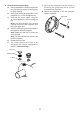
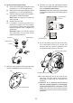
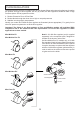
1. Carefully remove the concealing cap from the
control knob.
2. Unscrew the grubscrew using a 2.5 mm
hexagonal key (supplied) and pull off the
control knob(s).
Note! The ow control knob must be in the off
position in order to remove it.
Flow Control Knob
Temperature
Control Knob
Grubscrew
Grubscrew
Concealing Cap
Concealing Cap
Control Knob
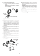
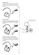
3. Carefully remove the concealing ring from the
concealing plate.
Concealing Ring
Concealing Plate
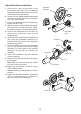
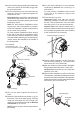
4. Determine the route for the hot and cold
supply pipework and for the outlet pipework.
When connecting to the BIV shower ttings it
is recommended that the outlet be positioned
to one side of the mixer. This is to prevent
the exible hose from obstructing the shower
controls (refer to illustration).
103 mm
Outlet Pipe BIV
Cold InletHot Inlet
Thermostatic
Mixer
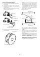
Alternative Pipe layouts
Outlet Pipe BIV
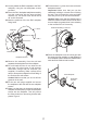
5. Mark the routes for the hot and cold supply
pipework at 103 mm centres (Hot - Left, Cold
- Right).
Note! If it is not possible to install the
mixer with this pipework conguration follow
instruction 6.
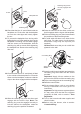
Falling Supplies: For falling supplies loosen
the grubscrew on each elbow using the 2.5 mm
hexagon key (supplied). Remove the elbows
and install on opposite sides.
Important! Make sure that the elbows are
pushed fully onto the mixer before tightening
the grubscrews, do not overtighten.