
Service manual


SECTION 7
PA-46-350P, MALIBU DESCR/OPERATION
SECTION 7
PA-46-350P, MALIBU DESCR/OPERATION
ISSUED: FEBRUARY 23, 1999 REPORT: VB-1710
7-7
ISSUED: FEBRUARY 23, 1999 REPORT: VB-1710
7-7
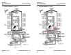
7.5 ENGINE AND PROPELLER (Continued)
Oil temperature and pressure information is available from separate gauges
located as part of the engine gauge stack. Engine crankcase gases are
discharged to an air/oil separator behind the left rear cylinder, and then vented
out the left exhaust stack.
PROPELLER
The propeller is a Hartzell composite, three blade, constant speed unit
with an 80-inch diameter. Constant propeller rotational speed (rpm) is
maintained by a balance of air load and engine rotational forces. The Hartzell
propeller governor, mounted on the left front of the engine, pressurizes and
regulates the flow of engine oil to a piston in the propeller dome. The piston
is linked by a sliding rod and fork arrangement to propeller blades. Governor
oil pressure against the piston works to increase propeller blade pitch, thus
decreasing propeller and engine rpm. Centrifugal twisting moments on the
propeller blades work to decrease propeller blade pitch and increase rpm.
Simple control of the interaction of these and other forces to maintain a
constant rpm is provided by the propeller control lever in the cockpit.
The propeller control lever, linked by cable to the propeller governor,
determines a wide range of in-flight rpm. Governor range is more limited
during ground operation. Pushing the lever forward selects increased or
higher rpm. Pulling the lever aft selects decreased or lower rpm. When in
flight the rpm should not fluctuate significantly from that set, regardless of
throttle setting.
The propeller may be operated within the full range of rpm indicated by
the tachometer, up to the red radial line. In cruise, always use the power
setting charts provided. Avoid exceeding maximum rpm and excessive
engine stress by moving propeller and throttle levers in smooth deliberate
motions. On cold days during run-up, exercise the propeller several times to
flow warm oil into the propeller hub. This assures propeller governing for
takeoff.
7.6 AIR INDUCTION SYSTEM
CAUTION
Alternate air is unfiltered. Use of alternate air
during ground or flight operations when dust or
other contaminants are present may result in
engine damage from particle ingestion.
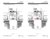
FOR REFERENCE ONLY
NOT FOR FLIGHT