ASI-Bridge CAM Guide to Installation and Operation M816-9900-102 7 Aug 2008 Miranda Technologies Inc. 3499 Douglas-B.-Floreani St-Laurent, Québec, Canada H4S 1Y6 Tel. 514-333-1772 Fax. 514-333-9828 www.miranda.com © 2008 Miranda Technologies Inc..
GUIDE TO INSTALLATION AND OPERATION Safety Compliance Information Safety Compliance This equipment complies with: - CSA C22.2 No. 60950-1-03 / Safety of Information Technology Equipment, Including Electrical Business Equipment. st UL 60950-1 (1 Edition) / Safety of Information Technology Equipment, Including Electrical Business Equipment. IEC 60950-1 (1st Edition) / Safety of Information Technology Equipment, Including Electrical Business Equipment.
Table of Contents 1 ASI-Bridge CAM: HDV to ASI Converter .................................................................... 1 1.1 Introduction .............................................................................................................................................. 1 1.2 Features ................................................................................................................................................... 1 1.3 Functional Block diagram...............................
GUIDE TO INSTALLATION AND OPERATION ASI-Bridge CAM
GUIDE TO INSTALLATION AND OPERATION 1 ASI-Bridge CAM: HDV to ASI Converter 1.1 Introduction The ASI-Bridge CAM is an HDV (MPEG2 on IEEE-1394) to ASI (MPEG2 on coaxial) converter. The ASI-Bridge CAM provides a convenient way of overcoming the operational limitations caused by the four meter maximum cable length of the IEEE-1394 interface. ASI signals can be carried for over 300 meters on coaxial cable, and over several kilometers by fiber.
GUIDE TO INSTALLATION AND OPERATION 1.3 Functional Block diagram Figure 1.1 Functional block diagram of the ASI-Bridge CAM 1.4 Application Examples Here are some examples of typical uses and applications for the ASI-Bridge CAM. 1.4.
GUIDE TO INSTALLATION AND OPERATION 1.4.2 On Set Dailies 1.4.3 D-VHS to On-Air Video Server Transfer 1.4.
GUIDE TO INSTALLATION AND OPERATION 1.4.
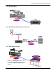
GUIDE TO INSTALLATION AND OPERATION 2 Installation 2.1 Physical Installation The ASI-Bridge CAM is designed to fit directly to the base of the camera, between the camera and its tripod or shoulder mount. ♦ ♦ ♦ Remove the camera from it’s tripod or shoulder mount. Install the ASI-Bridge CAM onto the base of the camera Reinstall the tripod or shoulder mount onto the base of the ASI-Bridge CAM 2.2 Connections Refer to figure 2.1 and to the descriptions below when connecting the ASI-Bridge CAM.
GUIDE TO INSTALLATION AND OPERATION 3 Operation Turn the ASI-Bridge CAM ON using the front-panel power button (see fig. 3.1) 3.1 User Interface The ASI-Bridge CAM has a very simple user interface, consisting of an ON/OFF pushbutton, and two status LEDs. 1 2 3 Figure 3.
GUIDE TO INSTALLATION AND OPERATION 3.2 Monitoring and Setting the Default HDV Status Note: The default HDV standard is important only when the ASI-Bridge CAM is being used with the Final Cut Pro software package on a Macintosh computer. In all other applications, the ASI-Bridge CAM detects the incoming transport stream format and configures itself automatically. The STATUS LED displays the default HDV standard at power-up as follows: The Status LED will: 1. Blink RED once 2.
GUIDE TO INSTALLATION AND OPERATION 4 Special Features and Notes Sony HDV cameras: In case of use with a Sony HDV camera that output a VBR stream without NULL packets, the ASI-Bridge CAM performs the following processes: • add the NULL packets to have a CBR 27Mbps stream. • Distribute the packets evenly in time to output the stream at 27Mbps CBR • Corrects the PCR packets timing information.
GUIDE TO INSTALLATION AND OPERATION 5 Specifications HDV INPUTS FORMATS MPEG2 HD TS at 19.2 and 25Mbps EN 50083-9, EN/ISO/IEC 13818-1(MPEG-2 TP 188 bytes), HDV_VER1.00_55: HD1(720p23.98/25/50/29.97/59.94) HD2(1080i50/59.