GUIDE TO INSTALLATION AND OPERATION Electromagnetic Compatibility This equipment has been tested for verification of compliance with FCC Part 15, Subpart B requirements for Class A digital devices. NOTE: This equipment has been tested and found to comply with the limits for a Class A digital device, pursuant to part 15 of the FCC Rules. These limits are designed to provide reasonable protection against harmful interference when the equipment is operated in a commercial environment.
GUIDE TO INSTALLATION AND OPERATION Table of Contents 1. DDA-1113 Digital Audio Distribution Amplifier ....................................................................... 5 1.1 1.2 1.3 1.4 2 Installation .................................................................................................................................. 7 2.1 2.2 2.3 3 Unpacking ...........................................................................................................................................
GUIDE TO INSTALLATION AND OPERATION DDA-1113
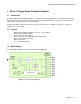
GUIDE TO INSTALLATION AND OPERATION 1. DDA-1113 Digital Audio Distribution Amplifier 1.1 Introduction The Digital Audio Distribution Amplifier DDA-1113 supports AES3-id 75 and provides up to 9 outputs, or 8 outputs with an input loop. The input features clock regeneration for reduced jitter and signal restoration. A signal detection stage permits control of the content of the audio signal. A multi-colored LED, visible with the door closed, reports the card status.
GUIDE TO INSTALLATION AND OPERATION SDA-1101 - SD DIGITAL VIDEO DISTRIBUTION AMPLIFIER 1.4 Front Card-edge Interface The front card-edge of the DDA-1113 incorporates two elements: Select Status Status LED (see section 3.1) Select Button (see section 3.2) DDA-1113 SELECT button Status LED Figure 1.
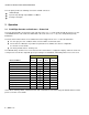
GUIDE TO INSTALLATION AND OPERATION 2 Installation 2.1 Unpacking Make sure the following items have been shipped with your DDA-1113. If any of the following items are missing, contact your distributor or Miranda Technologies Inc. For a DENSITÉ-2 frame: DDA-1113 Digital Audio Distribution Amplifier One of the DDA-1113 2RU rear panels Figure 2.1 DDA-1113 2RU Rear Panels For a DENSITÉ-3 frame: Figure 2.
GUIDE TO INSTALLATION AND OPERATION The rear panel provides the following connections on BNC connectors: 1 AES-3id input a passive loop-through only for DDA-1113-DRP/L 4 and up to 9 outputs 3 Operation 3.1 Card-Edge Controls and Indicators – Status Led The status monitor LED is located on the front card-edge of the DDA-1113, and is visible through the front access door of the DENSITÉ frame. This multi-color LED indicates the status of the DDA-1113 by color, and by flashing/steady illumination.
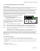
GUIDE TO INSTALLATION AND OPERATION 3.2 Local control using the Densité frame control panel 3.2.1 Overview Push the SELECT button on the DDA-1113 card edge (see Section 1.4) to assign the local control panel to operate the DDA-1113. Use the control panel buttons to navigate through the menu, as described below. All of the cards installed in a Densité frame are connected to the frame’s controller card, which handles all interaction between the cards and the outside world.
GUIDE TO INSTALLATION AND OPERATION o Adjust the Signal Delay and Signal Threshold to set the conditions of a No Signal alarm. A signal absence is declared when the level is lower than the threshold during the selected period. o Adjust the correction applied to the input signal: AUTO A START will initiate an automatic sequence, indicated by PROCESS. When the input status becomes correct it will stop and SUCCESS will be displayed.
GUIDE TO INSTALLATION AND OPERATION 3.3 iControl Interface The operation of the DDA-1113 may be controlled using Miranda’s iControl system. This section describes the control panels associated with the DDA-1113 and their uses. Please consult the iControl User’s Guide for information about setting up and operating iControl. In iControl Navigator or iControl Websites, double-click on the DDA-1113 icon to open the control panel.
GUIDE TO INSTALLATION AND OPERATION Mode AUTO A START will initiate an automatic sequence, indicated by PROCESS. When the input status becomes correct it will stop and SUCCESS will be displayed. FAIL will be displayed to indicate that no correction has been found that will yield a correct input status Input Load The Hi-Z selection is to be used along with a rear panel DDA-1113-DRP/L only to insure that the input signal is loaded only once at the end of the chain. 3.3.3 Alarms Tab Figure 3.
GUIDE TO INSTALLATION AND OPERATION Levels associated with these alarms: the pull-down lists may contain some or all of the following options: The alarm makes no contribution (black icon) The alarm is of minor importance (yellow icon) The alarm is of major importance (orange icon) The alarm is of critical importance (red icon) The alarm exists but has no effect (used for text and composite alarms) Shortcut: if you click in one of the Set all command under each major heading in the Status/Name line, you wil
GUIDE TO INSTALLATION AND OPERATION Get alarm keys Click this button to open a save dialog where you can save a file containing a list of all alarms on this card and their current values, along with an Alarm Key for each. The alarm keys are useful for system integration and troubleshooting. The file is saved in .csv format Figure 3.7 Get Alarm Keys 3.3.4 Info Tab The Info panel provides the user information about the DDA-1113.
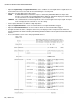
GUIDE TO INSTALLATION AND OPERATION 4 Specifications Input Signal Level Impedance Return loss Equalization AES3-id (SMPTE 276M) 0.1 to 7.0 Vpp 75 unbalanced or Hi-Z (selection by a command) 25 dB @6.144MHz With –SRP, -DRP or 2 x –DRP/L 0 to >2000 m Outputs Signal Level Impedance Rise/fall time Overshoot Return loss Jitter reduction Specific jitter AES3-id (SMPTE 276M) 1 Vpp 75 unbalanced 36/32 ns 0% 15 dB @6.144MHz 6 dB (@ 20 kHz) <0.