Intuition XG Advanced HD/SD Graphics Processor Installation & Quick Start Guide M848-9005-490 www.miranda.
Copyright & Trademark Notice Copyright © 2014, Miranda Technologies Partnership. All rights reserved. Belden, Belden Sending All The Right Signals, and the Belden logo are trademarks or registered trademarks of Belden Inc. or its affiliated companies in the United States and other jurisdictions. Miranda and Intuition XG are trademarks or registered trademarks of Miranda Technologies Partnership. Belden Inc.
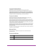
Revision History After the original release date, this document may be updated with edits and then rereleased. The following table tracks the versions of this document.
Safety Compliance This equipment complies with the requirements of the following standards for Safety of Information Technology Equipment: • CSA C22.2 no. 60950-1-07 (2nd Edition) • UL 60950-1 (2nd Edition) • IEC/EN 60950-1 (2nd Edition) Warning: An appropriately listed/certified main supply power cord must be used for the connection of the equipment to the main voltage at either 120V~ or 240V~ CAUTION: These servicing instructions are for use by qualified service personnel only.
WARNING Intuition XG devices contain Class 1 lasers, which are deemed safe under normal operating conditions. Standalone Equipment - Laser source(s) employed: CLASS 1 LASER PRODUCT APPAREIL A LASER DE CLASSE 1 WARNING Intuition XG devices contain a Lithium battery in the service access area, which should be replaced by the same type of battery.
TABLE OF CONTENTS Introduction .......................................................................................................................... 1-1 Intuition XG product description ........................................................................................................ 1-2 Overview of the Intuition XG-e chassis.............................................................................................. 1-6 Front panel components (Intuition XG-e)....................................
1 INTRODUCTION This guide provides basic Intuition XG product information and an orientation of the hardware components for all three (3) models of the Intuition XG (XG-e, XG-3U-e and XG-Dual-e). This guides also provides instructions for performing a first-time installation of the Intuition XG devices, as well as initial setup tasks to get the devices up and running. New Intuition XG devices are factory configured for standard rendering and playout workflows.
Introduction Intuition XG product description The Intuition XG graphics co-processor significantly extends the graphics and clip playout capabilities of master control switcher systems, like the Imagestore 750 or NV51000MC, by feeding the HD/SD fill/key inputs. It’s ideal for playout of the most advanced data-driven, channel branding and promotional graphics, including: “Coming up next” and episodic promos.
Introduction Intuition-XG-3U-e A single channel graphics co-processor, generally used upstream of a master control switcher like the Imagestore 750 or NV5100MC. Video In A • • • • • • • • • • • Fill Key Out A 3RU chassis with redundant power supply unit. 1 HD/SD video input, 1 HD/SD (Fill & Key) output A powerful, HD/SD character generator which allows the playout of virtually unlimited layers of animated text and dynamically updated text.
Introduction Intuition-XG-Dual-e A dual channel graphics co-processor, generally used upstream of a master control switcher like the Imagestore 750 or NV5100MC. Fill Key Video In A Video In B • • • • • • • • • • • Out A Fill Key Out B 3RU chassis with redundant power supply unit. 2 HD/SD video input, 2 HD/SD (Fill & Key) output A powerful, HD/SD character generator which allows the playout of virtually unlimited layers of animated text and dynamically updated text.
Introduction The following options are available on Intuition XG devices: VX-ClipPlayer Clip Player The Clip Player is an internal codec package for playing out multi-format video clips. VX-Audio-e Audio Processing The discrete audio I/O card allows the Intuition XG to capture, process and output discrete audio.
Introduction Overview of the Intuition XG-e chassis The Intuition XG-e is a single HD/SD channel playout server (1 HD/SD video input, 1 HDSDI Fill + Key output) that incorporates the Intuition XG graphics engine to rendering advanced graphics. Physically, the Intuition XG is a 1RU rackmount playout server with a single power supply unit and 1 TB of storage. The following table summarizes the Intuition XG-e’s physical dimensions and power consumption: Chassis FORM: 1U rackmount chassis HEIGHT: 1.
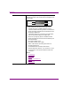
Introduction Front panel components (Intuition XG-e) The Intuition XG’s front panel provides convenient access to the SATA hard drives, two USB ports, a CD/DVD ROM drive, two fans, and a control panel containing five LEDs and two buttons for system monitoring and operation. Figure 1-1 identifies the LEDs, buttons and connectors on the front panel of the Intuition XG-e. Universal Info. LED USB 2.
Introduction Overview of the Intuition XG-3U/Dual chassis The Intuition XG unit is a 3RU rackmount rendering platform that incorporates redundant fans, three power supplies, and 1 TB RAID1-enabled storage (optional 2 TB RAID10 expansion). The only visible difference between the 3RU models of the Intuition XG is that the single channel model (XG-3U-e) has only one (1) discrete AES audio connector, while the dual channel model (XG-Dual-e) has two (2) discrete AES audio connectors.
Introduction Front panel components (Intuition XG-3U/Dual) The Intuition XG’s front panel provides convenient access to the hard drives, a CD/DVD ROM drive, and a control panel containing six LEDs and three buttons for system monitoring and operation. Figure 1-3 identifies each component on the Intuition XG’s front panel. SYSTEM ALERT / POWER FAILURE LAN 2 OVERHEAT / FAN FAIL HDD ACTIVITY LAN 1 POWER INDICATOR POWER CD/DVD ROM DRIVE HARD DRIVES FLOPPY DRIVE USB 2.0 CONNECTORS (2) Figure 1-3.
Introduction Rear panel components (Intuition XG-3U/Dual) The Intuition XG’s rear panel provides convenient access to the video card’s I/O connector, which provides 4 SD/HD SDI video outputs, a reference signal input, and AES audio input/output. The rear panel also provides access to the graphics card connector, as well as various I/O ports (RS-422, USB, Ethernet...etc.). Figure 1-4 identifies the components and connectors on the rear panel of the Intuition XG chassis.
2 INSTALLATION INSTRUCTIONS FOR THE INTUITION XG-E This chapter identifies and describes the tasks for performing a first-time installation of a factory-configured Intuition XG-e device. CAUTION Intuition XG devices should only be installed by trained personnel in a restricted access locations only. All health and safety regulations and precautions must be observed.
Installation instructions for the Intuition XG-e Unpacking and verifying the Intuition XG-e shipped items The Intuition XG-e device is packaged and shipped with the items listed in the table below. As you unpack the contents of the shipment, please verify the completeness and condition of the contents of the shipment. We also recommend that before attempting to install the unit, you use the table below to familiarize yourself with each of the items related to the Intuition XG-e.
Installation instructions for the Intuition XG-e VGA/DVI monitor adapter A computer monitor is required during the Intuition XG’s initial setup, which involves using the Intuition XG’s desktop applications, including Dashboard. The Intuition XG’s graphics card connectors allow you to connect to a DVI monitor. If you prefer, you can use the VGA/DVI adapter to connect the Intuition XG device to VGA monitor. Note that although there are two (2) DVI connectors, the Intuition XG can display to only one monitor.
Installation instructions for the Intuition XG-e ATI FirePro kit The ATI FirePro kit items are not required during the installation of a factory configured Intuition XG. The Intuition XG uses the ATI FirePro graphics card.
Installation instructions for the Intuition XG-e Mounting the Intuition XG-e chassis in a rack Included in the shipping package is a Rack mounting kit, which contains the rails, screws and washers required to mount the Intuition XG-e (1RU) chassis into an equipment rack. Note that the rails are designed to fit in racks with a depth of 28” to 33”.
Installation instructions for the Intuition XG-e 2-6 5. Repeat steps 2 to 4 for the other inner rail extension. 6. Each outer rail is in two sections that must be assembled before mounting onto the rack. a. Identify the left and right outer rails by examining the ends which bend outward. b. Slide the front section of the outer rail into the rear section of the outer rail. 7. Install the outer rails onto the rack. a.
Installation instructions for the Intuition XG-e CAUTION Due to the heavy weight of the Intuition XG device, ensure that the rack is securely anchored onto a unmovable surface or structure before installing the chassis into the rack. 8. Install the chassis into a rack. a. Confirm that chassis includes the inner rails and rail extensions. Also, confirm that the outer rails are installed on the rack. b. Line chassis rails with the front of the rack rails. c.
Installation instructions for the Intuition XG-e Cabling the Intuition XG-e unit Once the Intuition XG-e chassis is securely mounted in an equipment rack, you can connect the required cables to the rear connectors. Figure 2-1 and the cabling procedure provide stepby-step instructions for properly cabling the Intuition XG-e unit.
Installation instructions for the Intuition XG-e SDI OUT D /KEY Not used on an Intuition XG-e unit. ANALOG REF IN Connect to a house reference (Analog Blackburst or HD Tri-Level) to synchronize the phase timing video and graphics processing. ANALOG REF LOOP OUT Optional connection. Use to feed the reference signal from ANALOG REF IN to another piece of equipment. 2. Connect the Keyboard and Mouse to the USB connectors on the front or rear panel of the Intuition XG-e. 3.
3 INSTALLATION INSTRUCTIONS FOR THE INTUITION XG-3U/DUAL This chapter provides you with instructions for performing a first-time installation of a factory-configured Intuition XG-3U-e or Intuition XG-Dual-e devices. CAUTION Intuition XG devices should only be installed by trained personnel in a restricted access locations only. All health and safety regulations and precautions must be observed.
Installation instructions for the Intuition XG-3U/Dual Unpacking and verifying the Intuition XG-3U/Dual’s shipped items The Intuition XG device is packaged and shipped with the items listed in the table below. As you unpack the contents of the shipment, please verify the completeness and condition of the contents of your received shipment. We also recommend that before attempting to install the unit, you use the table below to familiarize yourself with each of the items related to the Intuition XG.
Installation instructions for the Intuition XG-3U/Dual Discrete (AES) audio breakout cable Single channel Intuition XG units (XG-3U-e) have one discrete (AES) audio connector, while dual channel Intuition XG units (XGDual-e) have two discrete (AES) audio connectors. For each physical SDI video output, there will be a discrete audio breakout cable. Each discrete audio breakout cable contains 4 BNC inputs and 8 BNC outputs. Each BNC connector represents 1 stereo pair (2 channels) of digital AES/EBU audio.
Installation instructions for the Intuition XG-3U/Dual System Recovery DVD package 2 x System Recovery DVDs These DVDs can be used to restore the Intuition XG unit to its original factory default configuration. Note that one of the DVDs has a sticker with the Intuition XG’s serial number, which identifies that particular Intuition XG unit. Store these the System Recovery DVDs in a safe location. Do not misplace.
Installation instructions for the Intuition XG-3U/Dual SuperMicro User’s Manual and Bootable CD These SuperMicro items are not required during the installation of a factory configured Intuition XG. The Intuition XG uses SuperMicro’s motherboard. As such, the documentation and bootable CD (drivers & utilities) have been included in the Intuition XG shipping package.
Installation instructions for the Intuition XG-3U/Dual Mounting the Intuition XG-3U/Dual chassis in a rack Included in the shipping package is a Rack mounting kit, which contains the rails, screws and washers required to mount the Intuition XG chassis into an equipment rack. Note that the rails are designed to fit in racks with a depth of 28” to 33”. Due to the heavy weigh of the unit, the rack in which the Intuition XG unit will be installed should be anchored to the building’s structure.
Installation instructions for the Intuition XG-3U/Dual 3. Locate the five rail buttons on each side of the chassis and locate the five corresponding holes on each of the inner rails. (*Please note that one end of the hole is larger than the other end of the hole.) 4. Align the larger end of each hole against its corresponding button. Once all aligned, push the holes toward their corresponding buttons and the rail is placed on the chassis. 5.
Installation instructions for the Intuition XG-3U/Dual 7. After you have installed the inner rails on the chassis, you are ready to install the outer rails of the rail assemblies to the rack. In the package, locate a pair of front (-short) and rear (-long) brackets. Please note that the brackets are marked with Up/Front arrows (-front) and Up/Rear arrows (-rear). 8. Secure the front (-short) bracket (marked with the Up/Front arrows) to the outer rail with two Type G screws. 9.
Installation instructions for the Intuition XG-3U/Dual 13. Slide the Intuition XG chassis into the rack as shown below. The chassis may not slide into the rack smoothly or easily when installed for the first time. Adjustments to the slide assemblies might be necessary to achieve a smooth insertion. CAUTION Due to the heavy weight of the Intuition XG device, ensure that the rack is securely anchored onto a unmovable surface or structure before installing the chassis into the rack.
Installation instructions for the Intuition XG-3U/Dual Cabling the Intuition XG-3U/Dual unit Once the Intuition XG chassis is securely mounted in an equipment rack, you can connect the required cables to the rear connectors of the Intuition XG unit. Figure 3-1 and the cabling procedure provide step-by-step instructions for properly cabling the Intuition XG unit.
Installation instructions for the Intuition XG-3U/Dual To cable the Intuition XG-3U-e or the Intuition XG-Dual-e: 1. Connect the three (3) AC power cables to the power supply sockets on the rear panel of the Intuition XG chassis. WARNING DO NOT plug the power cables into AC power sockets yet. 2. 3. Connect the Keyboard and Mouse to the USB connectors on the front or rear panel of the Intuition XG.
Installation instructions for the Intuition XG-3U/Dual SDI OUT B Second output channel connection for dual channel Intuition XG units (XG-Dual-e). For the purposes of this setup procedure, connect this cable to a broadcast monitor. Not used on single channel Intuition XG units (X-3U-e). 6. SDI OUT C /KEY The matching key signal for SDI OUT A. SDI OUT D /KEY SDI Out B (Fill 2) is the second output channel on the Intuition XGDual-e model.
Installation instructions for the Intuition XG-3U/Dual 8. 9. Optional: Connect a Time Code Generator to the Time Code card’s BNC connector on the rear panel of the Intuition XG. The Time Code Card is a hardware option on the Intuition XG (see page 1-5), which allows you to lock the Intuition XG’s system clock to an external timecode. The Time Code card reads Longitudinal Time Code (LTC) from the signal present at the BNC connector.
4 QUICK START INSTRUCTIONS This chapter provides you with instructions for performing the initial setup tasks to get the a newly installed Intuition XG device up and running. The procedure concludes by verifying the installation by previewing the playout of an asset in Intuition XG’s Live Window and a broadcast monitor. The following table summarizes the tasks that you must perform to quickly start up a factoryconfigured Intuition XG device.
Quick start instructions Starting the Intuition XG Once the Intuition XG is properly racked and cabled, you can make the power connections and you can perform the first-time start up of the Intuition XG unit. 1. Plug the monitor’s power cable into a power socket and power it on. 2. Plug the Intuition XG’s power supply cable(s) into a power socket. 3. Power on the Intuition XG unit by pressing the POWER button on the unit’s front panel.
Quick start instructions Xplay Xplay is the playout control application that the master control system or device uses to control the playout of video and graphics on the Intuition XG device. Whether the Intuition XG is a single or dual channel model, only one instance of Xplay is used to control the Intuition XG device’s output. Vertigo Command Shell The Vertigo Command Shell window allows you to perform some basic command tasks like opening Windows Explorer and shutdown/reboot the Intuition XG device.
Quick start instructions Assigning a new IP address to the Intuition XG device Factory configured Intuition XG units are shipped with a dynamic IP address. Using DHCP is not recommend, so you must assign a new static IP Address to the Intuition XG device. To change the Intuition XG’s current dynamic IP address to a static IP address: 1. In the Vertigo Command Shell, type ipconfig and take note of the current IP configuration. 2.
Quick start instructions Verifying the installation and setup by previewing the playout To verify that the Intuition XG is properly connected and operating, we recommend that you use the local copy of Xplay to load and playout an asset in the Live window and broadcast monitor associated with the Intuition XG’s Channel A. For dual channel Intuition XG devices, we recommend performing the same verification tasks on Channel B.
Quick start instructions Enable the Intuition XG’s Live window For installation and troubleshooting purposes, the Intuition XG is equipped with a preview window called the Live Window. The Live Window allows you to display a representation of the output channel’s playout directly on the Intuition XG’s desktop. To enable the device channel’s Live Window: 1. If Channel A’s Dashboard is not already open, select the TOOLS>LAUNCH DASHBOARD menu command in the Intuition XG’s Control Panel for Channel A.
Quick start instructions Use Xplay to playout a graphic To verify that the Intuition XG is properly connected and playing out, the following procedures has you add a template asset to the playlist, then cue and take the asset so that it plays out in the Live window, as well as the broadcast monitor. NOTE These instructions describe playing out on the Intuition XG’s primary output (channel A).
Quick start instructions Completing the quick start procedure With the Intuition XG now capable of playing out graphics, we recommend that you disable the Live Windows as they put an unnecessary burden on the system’s resources during on-air playout. Since the mouse, keyboard and DVI monitor are only used during the setup and configuration procedures, you can also disconnect these peripherals from the Intuition XG unit. To disable the Live Window: 1.
5 NEED FURTHER ASSISTANCE? Technical Support For technical assistance, please contact the Miranda Technical support centre nearest you: Americas Office hours: 9:00 a.m. - 9:00 p.m. (EST) Telephone: +1-800-224-7882 Fax: +1-514-335-1614 e-mail: support@miranda.com Asia Office hours: 9:00 am - 5:00 pm (GMT+8) Telephone: +852-2539-6987 Fax: +852-2539-0804 e-mail: asiatech@miranda.com China Telephone: +86-10-5873-1814 e-mail: asiatech@miranda.com Europe, Middle East, Africa, UK Office hours: 9:00 a.m. - 6:00 p.
Need further assistance? Related Documentation To access the most recent updates to this document, or to access other Vertigo Suite user documentation, please visit the VERTIGO DOCUMENTATION section on MIranda’s TECHNICAL SUPPORT SERVICES web site (http://www.miranda.com/support/). Customer Service and Sales For customer service or sales information, please contact a Miranda Technologies sales office. Visit our web site at http://www.miranda.com/contact.php?link=worldwide to find office nearest to you.