DENSITÉ series IRD-3802 Integrated Receiver and Decoder Guide to Installation and Operation M837-9600-100 18 Sep 2008 Miranda Technologies Inc. 3499 Douglas-B.-Floreani St-Laurent, Québec, Canada H4S 1Y6 Tel. 514-333-1772 Fax. 514-333-9828 www.miranda.com © 2008 Miranda Technologies Inc..
GUIDE TO INSTALLATION AND OPERATION Safety Compliance Information Safety Compliance This equipment complies with: - CSA C22.2 No. 60950-1-03 / Safety of Information Technology Equipment, Including Electrical Business Equipment. UL 60950-1 (1st Edition) / Safety of Information Technology Equipment, Including Electrical Business Equipment. st IEC 60950-1 (1 Edition) / Safety of Information Technology Equipment, Including Electrical Business Equipment.
GUIDE TO INSTALLATION AND OPERATION Table of Contents 1 IRD-3802 HD/SD MPEG Decoder with ASI and GigE IP inputs...............................................5 1.1 1.2 1.3 1.4 1.5 2 Installation ..................................................................................................................................9 2.1 2.2 2.3 2.4 3 3.4 Control options ..................................................................................................................................
GUIDE TO INSTALLATION AND OPERATION IRD-3802
GUIDE TO INSTALLATION AND OPERATION 1 IRD-3802 HD/SD MPEG Decoder with ASI and GigE IP inputs 1.1 Introduction The IRD-3802 combines MPEG-2 and H.264 decoding of ASI and IP transport streams to either HD or SD, with processing of key video and audio parameters and signal probing functions for feed aggregation, distribution, and monitoring applications by broadcasters and TV services providers.
GUIDE TO INSTALLATION AND OPERATION Extensive Video Decoding • The IRD can decode signals in various resolutions extending to 1920x1080i, and at various frequencies. Output formats include: o 1920x1080i 59.94 o 1920x1080i 50 o 1280x720p 59.94 o 1280x720p 50 o 720x486i 59.94 o 720x576i 50 Comprehensive Audio Decoding • Decoding of MPEG-1 Layer 2 stereo audio • Decoding of MPEG 2 audio • Support of Dolby Digital (AC-3) 2.0 audio • Optional decoding of Dolby Digital (AC-3) 5.
GUIDE TO INSTALLATION AND OPERATION o Rating and other RRT data o TSID Transport Stream Probing and Alarming • Transport Stream (TS) monitoring and alarming: o TR 101 290 Priority 1 and Priority 2 alarming on key parameters o TS Bit rate o TS ID and number of programs as identified in PAT o Network ID and name as identified in NIT o Logging of alarms using iControl • Detailed TS structure reporting using graphical and hierarchical views 1.3 Applications • Decoding of MPEG-2 and H.
GUIDE TO INSTALLATION AND OPERATION 1.5 Front Card-edge Interface The front card-edge of the IRD-3802 incorporates two elements: Select Status LED (see section 3.2) Select Button (see section 3.3) Status • • IRD-3802 Select Button Status LED Figure 1.
GUIDE TO INSTALLATION AND OPERATION 2 Installation 2.1 Unpacking Make sure the following items have been shipped with your IRD-3802. If any of the following items are missing, contact your distributor or Miranda Technologies Inc. • IRD-3802 Integrated Receiver and Decoder • IRD-3802-3DRP Rear Panel (see figure 2.1) 2.2 Installation in the Densité frame The IRD-3802 and its associated rear connector rear panel must be mounted in a Densité3 frame.
GUIDE TO INSTALLATION AND OPERATION 2.4 Connections The rear panel connections are as follows: • REF IN – External reference input For external synchronization, connect a black studio reference signal to the BNC labeled REF IN. The reference input must conform to SMPTE 170M/SMPTE 318M/ITU 624-4/BUT 470-6 for standard definition signals and SMPTE 274M / SMPTE 296M for high definition signals and is used to phase the HD/SD SDI outputs to the studio.
GUIDE TO INSTALLATION AND OPERATION 3 Operation 3.1 Control options The IRD-3802 can be controlled in two different ways: • The local control panel and its push-buttons can be used to move through a menu of parameters and to adjust parameter values (see section 3.3). • Miranda’s iControl system can be used to access the card’s operating parameters from a remote computer, using a convenient graphical user interface (GUI). (see section 3.4) 3.
GUIDE TO INSTALLATION AND OPERATION 3.3 Local control using the Densité frame control panel 3.3.1 Overview Push the SELECT button on the IRD-3802 card edge (Section 1.5) to assign the local control panel to operate the IRD-3802. Use the control panel buttons to navigate through the menu, as described below. All of the cards installed in a Densité frame are connected to the frame’s controller card, which handles all interaction between the cards and the outside world.
GUIDE TO INSTALLATION AND OPERATION 3.4 Remote control using iControl The operation of the IRD-3802 may be controlled using Miranda’s iControl system. • • This manual describes the control panels associated with the IRD-3802 and their use. Please consult the iControl User’s Guide for information about setting up and operating iControl. In iControl Navigator or iControl Websites, double-click on the IRD-3802 icon to open the control panel. 3.4.
GUIDE TO INSTALLATION AND OPERATION Icon #2 – TS Input status Transport Stream detected and OK.
GUIDE TO INSTALLATION AND OPERATION Icon #6 – Secondary Audio status Operation mode: process – normal processing of the input signal (green) No audio in program (yellow) No signal (gray Icon #7 – Audio Sync Locked with Video (green) Free run (yellow) Icon #8 – TS Limit No errors (green) Errors detected (red) Icon #9 – Reference Locked to external reference (green) • Mouse-over the icon to see a description of the reference in use Reference missing (red) No frame sync option activated (gray) Move
GUIDE TO INSTALLATION AND OPERATION 2. The left-hand side of the panel contains a series of buttons that control the contents of the main window (section 3). Click on one to access the indicated controls. The selected button is highlighted (darker) and the main panel heading matches the button name. 3. This section contains the main operating controls and displays for managing the IRD-3802’s feature set. The contents are selected by clicking a button on the left-hand side of the screen.
GUIDE TO INSTALLATION AND OPERATION Currently Selected Service The Data windows and status icons in this area report on various aspects of the currently-selected service Service Use the MPEG Synchronization pulldown to select the synchronization mode: • OFF – no clock recovery from PCR packet; local clock used • Auto – try to recover the clock if possible (see status icon) If there are lots of errors in the stream, or the IRD3802 cannot lock easily on the signal, set to OFF to avoid switching back and fort
GUIDE TO INSTALLATION AND OPERATION Insertion Line: The Insertion line is used to select on which line in the VANC the AFD packet (SMPTE 2016) will be inserted. It is not necessary to specify the detection line since the card will automatically detect the incoming packet.
GUIDE TO INSTALLATION AND OPERATION Metadata tab The six pulldowns on this panel provide the resources to configure metadata processing on this IRD-3802.
GUIDE TO INSTALLATION AND OPERATION CVBS tab This tab contains controls to configure the analog video output signal. Blanking Mode Use the pulldown to select whether the blanking on the output signal will be narrow or wide Luma Range Use the pulldown to choose whether to restrict the Luma signal range to normal limits, or to allow super whites and blacks (i.e. a much expanded range).
GUIDE TO INSTALLATION AND OPERATION AC3 Downmix mode – select the downmix mode from these options: Audio 1: • OFF • • Lt/Rt – Dolby “unofficial” pro-logic compatible Lo/Ro – normal stereo Audio 2: • • Lt/Rt – Dolby “unofficial” pro-logic compatible Lo/Ro – normal stereo Audio Insert Use the pulldown to select whether audio embedding is ON or OFF. Status tab This tab contains text boxes and status icons that indicate the current status of the IRD-3802’s audio processing. Figure 3.
GUIDE TO INSTALLATION AND OPERATION • 625 from URS (Universal Reference Signal) – selects the internal reference (625) from the backplane • Input – uses the currently-selected input signal. The Used Reference box shows the reference currently in use, which is helpful in Auto mode Vertical (lines) With this adjustment, a value ranging from 0 to +200 lines, compared to the reference or the processing delay, may be set. This adjustment can be used in conjunction with the horizontal timing adjustment.
GUIDE TO INSTALLATION AND OPERATION TR 101 290 tab This tab shows the results of the tests against the TR 101 290 standard Click in the checkbox at the bottom to enable or disable display updating (about once per second) Figure 3.14 TR 101 290 tab Unref_PID tab This tab provides a list of all unreferenced PIDs found in the incoming service. Figure 3.
GUIDE TO INSTALLATION AND OPERATION Pie Chart tab This tab displays the incoming service in the form of a pie chart, with color-coded segments representing the various elements in the service. • This representation illustrates the bandwidth distribution within the service. The table below the chart shows all of the elements, identifying each by name, PID and bandwidth.
GUIDE TO INSTALLATION AND OPERATION 3.4.8 The Test panel Use the Color Bars checkbox to turn the Test function ON or OFF • When checked, the output signal is replaced by Color Bars. • When unchecked, the normal program signal is present at the output. Figure 3.12 The Test panel 3.4.
GUIDE TO INSTALLATION AND OPERATION IP Config DHCP checkbox The "DHCP" parameter activates or deactivates dynamic network addressing. When activated, it allows a server to dynamically attribute an IP address and configuration information to the IRD-3802. When the checkbox is selected, the static network parameters become unavailable. IP Address Mask Gateway static network parameters Enter the values directly in the data boxes.
GUIDE TO INSTALLATION AND OPERATION 3.4.10 The Factory/Presets panel This panel provides resources for saving, restoring and transferring the configuration settings of this IRD-3802. Load Factory The IRD-3802 maintains a “Factory Default” alignment in its memory, to which it can be restored at any time. • Click the Load Factory button to restore the card to its Factory default alignment. User Presets The User Preset controls allow the user to save and recover all configuration settings on the card.
GUIDE TO INSTALLATION AND OPERATION Copy Profile From: This line shows this IRD-3802 card, and identifies it by App server, Densité frame and slot number, card type and firmware version. The Profile column has a pulldown that allows you to select which profiles you will work with, and gives these choices: • Current, User1, User2, User3, User4, User5, ALL The Select column includes a checkbox, preselected as checked, to confirm that you want to work with the current card.
GUIDE TO INSTALLATION AND OPERATION Copy profile to section This line shows other IRD-3802 cards that are available on the iControl network, each identified by App server, Densité frame and slot number, card type and firmware version. The Profile column shows the same information as is shown for the current card in the Copy profile from line, i.e.
GUIDE TO INSTALLATION AND OPERATION Up/Down/Cross option This option enables up-conversion (SD-to-HD), down-conversion (HD-to-SD) and cross-conversion (HD-to-HD) functionality on the IRD-3802. To activate this option, you must: • Obtain a licence key from Miranda Technologies Inc. • Type the licence key in the box • Click on ENABLE OPTION to enable the option’s features. Figure 3.
GUIDE TO INSTALLATION AND OPERATION TS Probing option This option activates the Transport Stream probing functions of the IRD-3802. To activate this option, you must: • Obtain a licence key from Miranda Technologies Inc. • Type the licence key in the box • Click on ENABLE OPTION to enable the option’s features. Figure 3.27 Options panel – TS Probing Dolby 5.1 option This option enables the Dolby 5.1 output on 6 discrete channels Note – Dolby 5.
GUIDE TO INSTALLATION AND OPERATION 3.4.12 The Alarm Config panel This panel allows the alarm reporting of the IRD-3802 to be configured. The panel opens in a new window when the button is clicked, and can be resized if needed. The panel is organized in columns. Status/Name This contains an expandable tree listing all the alarms reported by this IRD-3802 card.
GUIDE TO INSTALLATION AND OPERATION • GSM Contribution This column allows configuration of the contribution of each individual alarm to the GSM Alarm Status associated with this card. GSM is a dynamic register of all iControl system alarms, and is also an alarm provider for external applications.
GUIDE TO INSTALLATION AND OPERATION 3.4.13 The Info panel Info tab When the IRD-3802 is included in an iControl environment, certain information about the card should be available to the iControl system. The user can enter labels and comments that will make this card easy to identify in a complex setup. This information is entered via the Info control panel. This panel also shows other information about the card.
GUIDE TO INSTALLATION AND OPERATION • Remote System Administration – opens the Joining Locators data box, which lists remote lookup services to which this IRD3802 is registered. Add: Force the iControl service for this IRD-3802 to register itself on a user-specified Jini lookup service, using the following syntax in the data box: jini:// where <ïp_address> is the ip address of the server running the lookup service, e.g.: Figure 3.
GUIDE TO INSTALLATION AND OPERATION 4 User Reference Guide 4.1 Decoding MPEG Transport Streams The user can input DVB-ASI signals up to 80Mbps on either ASI input connector. Alternatively, the Ethernet can be configured to receive an IP stream (see section 3.4.9). To select an input, go to the Input Menu into Input Selection. Once a valid transport stream signal enters the decoder, the first valid service found is decoded automatically if no selection was previously made.
GUIDE TO INSTALLATION AND OPERATION The following audio coding formats are currently supported: • • • AC3 audio up to 5.1 channels MPEG1 Layer II MPEG2 Audio The first audio can be embedded as 5.1 discrete channels (the Dolby option is required to get discreet channels; otherwise you get 2 down-mixed channels) while the second audio is always output as 2 channels. Down mix mode can be selected between Lt/Rt or Lo/Ro modes independently for both audios.
GUIDE TO INSTALLATION AND OPERATION Note that the PSIP RTT tables are not extracted. The rating information comes from the standard MPAA and other North American rating systems. Closed captioning data must be present in the MPEG video stream or XDS data will not be inserted at the output 4.5 Using the Up/Down/Cross Option The Up/Down/Cross Option allows the user to re-scale the input signal to any supported output resolution.
GUIDE TO INSTALLATION AND OPERATION In any case, the embedded AFD flag at the output follows any transformation that might have occurred. Therefore should the picture be rescaled, the embedded AFD reflects the actual status of the picture at the output. For example, an MPEG signal in full 16:9 (AFD code 8) down converted to SD 4:3 in letterbox will have the AFD flag 10 inserted to signal letterbox. Some restrictions apply to firmware revisions less than 211.
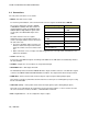
GUIDE TO INSTALLATION AND OPERATION Input signal 4:3 Output signal 16:9 4:3 Full frame image in a 4:3 frame 4:3 Full frame image in a 4:3 frame 4:3 Pillar-box image in 16:9 frame (4:3_8) 4:3 Full frame image in a 4:3 frame (use preferred 4:3_8 code instead) (4:3_8) 4:3 Full frame image in a 4:3 frame (16:9_9) 4:3 Pillar-box image in 16:9 frame (4:3_9) (16:9_9) (4:3_9) 16:9 Letterbox image in 4:3 frame 16:9 Letterbox image in 4:3 frame 16:9 Full frame image in a 16:9 frame (4:3_10) 14:9 Lette
GUIDE TO INSTALLATION AND OPERATION Input signal 4:3 Output signal 16:9 16:9 Full frame image in a 16:9 frame (use preferred 16:9_8 flag instead) 16:9 Letterbox image in 4:3 frame 16:9 Full frame image in a 16:9 frame (16:9_2) 14:9 Pillar-box image in a 16:9 frame (use preferred 16:9_11 flag instead) (4:3_10) 14:9 Letterbox image in a 4:3 frame (16:9_2) 14:9 Pillar-box image in a 16:9 frame (16:9_3) > 16:9 Letterbox (center) image in a 16:9 frame (4:3_11) 16:9 Letterbox image in 4:3 frame (16:9
GUIDE TO INSTALLATION AND OPERATION Input signal 4:3 Output signal 16:9 4:3 Pillar-box image Shoot and protect 14:9 in a 16:9 frame 4:3 Image shoot and protect 14:9 in a 4:3 frame 14:9 Pillar-box image in a 16:9 frame (16:9_13) 16:9 Image shoot and protect 14:9 in a 16:9 frame (4:3_13) 14:9 Letterbox image in a 4:3 frame (16:9_11) 16:9 Image shoot and protect 14:9 in a 16:9 frame (16:9_14) 16:9 Image shoot and protect 4:3 in a 16:9 frame (4:3_11) 4:3 Full frame image in a 4:3 frame (16:9_14) 16
GUIDE TO INSTALLATION AND OPERATION 5 Specifications ASI INPUTS QUANTITY/CONNECTOR: STANDARDS: DATA BITRATE: MODE: TS PACKET LENGTH: RETURN LOSS: Two inputs with BNC connectors EN50083-9 (V2:3/98) DVB ASI DVB ASI: Up to 80 Mbps Burst and byte supported 188/204 byte packets > 15 dB up to 270 MHz ASI OUTPUT QUANTITY/CONNECTOR: One output with BNC connector IP INPUT/OUTPUT QUANTITY/CONNECTOR: STANDARDS: STREAM PROTOCOLS: One Gigabit Ethernet with RJ45 connector IEEE 802.
GUIDE TO INSTALLATION AND OPERATION MONITORING OUTPUTS ANALOG VIDEO: ANALOG AUDIO: NTSC 525/60, PAL (625/50) With one BNC connector Balanced analog audio with two RCA connectors VIDEO AND TS METADATA CC DATA EXTRACTION: CC EMBEDDING: TIME CODE: PSIP: NTSC CC1 and CC2 as per EIA-608B DTV CC: EIA-608B compliant bytes of EIA-708B CC Embedding as per SMPTE-334M SMPTE 12M ATSC PSIP Standard A/65 REFERENCE INPUT REFERENCE INPUT: SIGNAL: RETURN LOSS: One input with BNC connector SMPTE 170M/SMPTE 318M/ITU 624
GUIDE TO INSTALLATION AND OPERATION ANNEX – Local Control Panel User Interface IRD-3802 LEV 1 STATUS LEV 2 CARD STATUS LEV 3 DEVICE STATUS LEV 4 Settings NO REAR, WRONG REAR, SYS OK SELECTED INPUT DVB-ASI1, DVB-ASI2*, ETHERNET*, TUNER* TS TYPE NO SIGNAL, SIGNAL ERR, ATSC, DVB, ISO13818-1 OUTPUT FORMAT () REF MISMATCH REFERENCE STATUS* INTERNAL, EXTERNAL, URS 1080i50,720p50,720p59.94,525,625,1080i59.
GUIDE TO INSTALLATION AND OPERATION VIDEO MENU AUDIO MENU DEFAULT MASK xxx.xxx.xxx.xxx DEFAULT GATEWAY xxx.xxx.xxx.xxx PORT DIRECTION DISABLED, INPUT*, OUTPUT UNICAST DEST. xxx.xxx.xxx.xxx MULTICAST ADDR xxx.xxx.xxx.xxx PORT NUMBER xxxx ENCAPSULATION RTP, UDP STREAM MODE UNICAST,MULTICAST FEC OFF, D=x L=x OUTPUT ON ERROR Freeze, Black OUTPUT FORMAT As Input. 1080i, 720p, SD AFD MODE AUTO, FORCED DEFAULT AFD CODE numbers from 8 to 15 ASP.
GUIDE TO INSTALLATION AND OPERATION ALARM MENU NO TS INPUT NO VIDEO SIGNAL NO AUDIO SIGNAL NO REFERENCE REF MISMATCH PROGRAM SYNCHRO TS LIMITS VERSION ALARM LEVEL OFF, YELLOW, RED, FLASH RED ALARM REPORT NONE, GPI ALARM LEVEL OFF, YELLOW, RED, FLASH RED ALARM REPORT NONE, GPI ALARM LEVEL OFF, YELLOW, RED, FLASH RED ALARM REPORT NONE, GPI ALARM LEVEL OFF, YELLOW, RED, FLASH RED ALARM REPORT NONE, GPI ALARM LEVEL OFF, YELLOW, RED, FLASH RED ALARM REPORT NONE, GPI ALARM LEVEL OFF