DENSITÉ series FLO-1601 L-Band Fiber Transmitter Guide to Installation and Operation M830-9900-100 9 Nov 2007 Miranda Technologies Inc. 3499 Douglas-B.-Floreani St-Laurent, Québec, Canada H4S 1Y6 Tel. 514-333-1772 Fax. 514-333-9828 www.miranda.com © 2007 Miranda Technologies Inc.
GUIDE TO INSTALLATION AND OPERATION Safety Compliance Information Safety Compliance This equipment complies with: - CSA C22.2 No. 60950-1-03 / Safety of Information Technology Equipment, Including Electrical Business Equipment. UL 60950-1 (1st Edition) / Safety of Information Technology Equipment, Including Electrical Business Equipment. st IEC 60950-1 (1 Edition) / Safety of Information Technology Equipment, Including Electrical Business Equipment.
GUIDE TO INSTALLATION AND OPERATION Table of Contents 1 FLO-1601 L-Band Fiber Transmitter .........................................................................................1 1.1 1.2 1.3 1.4 2 Installation ..................................................................................................................................3 2.1 2.2 2.3 3 Unpacking ..........................................................................................................................................
GUIDE TO INSTALLATION AND OPERATION FLO-1601
GUIDE TO INSTALLATION AND OPERATION 1 FLO-1601 L-Band Fiber Transmitter 1.1 Introduction The FLO-1601 is a fiber optic transmitter that allows an L-band satellite signal to be sent over a single mode fiber. The fiber transmission is totally protocol transparent and the FLO-1601 maintains high signal fidelity over the whole transmission. The FLO-1601 accepts a wide range RF level input and provides automatic gain control (AGC).
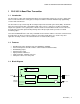
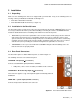
GUIDE TO INSTALLATION AND OPERATION 1.4 Front Card-edge Interface The front card-edge of the FLO-1601 incorporates two elements: Select Status LED (see section 3.2) Select Button (see section 3.3) Status • • FLO-1601 SELECT button Status LED Figure 1.
GUIDE TO INSTALLATION AND OPERATION 2 Installation 2.1 Unpacking Make sure the following items have been shipped with your FLO-1601. If any of the following items are missing, contact your distributor or Miranda Technologies Inc. • FLO-1601 L-Band Fiber Transmitter • FLO-1601-DRP Double Rear Panel (see figure 2.1) 2.2 Installation in the Densité frame The FLO-1601 and its associated rear connector rear panel must be mounted in a DENSITÉ frame.
GUIDE TO INSTALLATION AND OPERATION 3 Operation 3.1 Control options The FLO-1601 can be controlled in three different ways: • The local control panel and its push-buttons can be used to move through a menu of parameters and to adjust parameter values (see section 3.3). • Miranda’s RCP-100 remote control panel can be used to access the same menu structure from a remote location (see section 3.4).
GUIDE TO INSTALLATION AND OPERATION 3.3 Local control using the Densité frame control panel 3.3.1 Overview Push the SELECT button on the FLO-1601 card edge (see Section 1.4) to assign the local control panel to operate the FLO-1601. Use the control panel buttons to navigate through the menu, as described below. All of the cards installed in a Densité frame are connected to the frame’s controller card, which handles all interaction between the cards and the outside world.
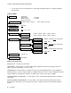
GUIDE TO INSTALLATION AND OPERATION • Use the keys on the local control panel to step through the displayed menu to configure and adjust the FLO-1601. FLO-1601 MENU STATUS STATUS OK NO RF INPUT WEAK RF INPUT OPTICAL OUT FAIL (< -60 dBm) (< -55 dBm) RF SIG STRENGTH [-60 dBm, -59 dBm, -58 dBm,…..
GUIDE TO INSTALLATION AND OPERATION FACTORY DEFAULT – activate this command to restore the configuration of the FLO-1601 to a factory default state. The settings of the factory default state are indicated in the menu by an underline in the list of possible values in square brackets, e.g. [OFF, ON] indicates that OFF is the factory default value. 3.4 Remote Control Using the RCP-100 The FLO-1601 can be controlled through a menu accessible using Miranda’s RCP-100 remote control panel.
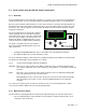
GUIDE TO INSTALLATION AND OPERATION 4 Specifications RF INPUT Frequency Range Connector Return loss Input power range Maximum input level 950Mhz – 2150MHz 75 Ohm “F” connector > 10dB across the whole frequency range (950-2150MHz) -60dBm to -20dBm -20dBm OUTPUTS RF Monitoring Output Frequency Range Connector Return loss Output Level 950Mhz – 2150MHz 75 Ohm “F” connector > 10dB across the whole frequency range (950-2150MHz) same as input signal Optical Output Laser Optical Wavelength Connector Output Pow