Vertigo XG Advanced HD/SD Graphics Processor Installation & Quick Start Guide M848-2705-480 w w w . m i r a n d a .
Vertigo XG21-e Vertigo XG22-e Vertigo Suite v4.
Copyright Notice © 2012 Miranda Technologies Inc. All rights reserved. Third Party Trademarks All other brand names, product names or trademarks belong to their respective holders. Usage Agreement Please read the following terms and conditions carefully. By using the Vertigo XG Installation & Quick Start Guide, you agree to the following terms and conditions: Miranda Technologies Inc.
Safety Compliance This equipment complies with the requirements of the following standards for Safety of Information Technology Equipment: • CSA C22.2 no. 60950-1-07 (2nd Edition) • UL 60950-1 (2nd Edition) • IEC/EN 60950-1 (2nd Edition) Warning: An appropriately listed/certified main supply power cord must be used for the connection of the equipment to the main voltage at either 120V~ or 240V~ CAUTION: These servicing instructions are for use by qualified service personnel only.
WARNING Vertigo XG devices contain Class 1 lasers, which are deemed safe under normal operating conditions.
TABLE OF CONTENTS Introduction .......................................................................................................................... 1-1 Vertigo XG product description.......................................................................................................... 1-2 Overview of the Vertigo XG chassis .................................................................................................. 1-4 Front panel components ....................................................
Table of Contents TOC-2 Vertigo XG Installation & Quick Start Guide
1 INTRODUCTION This guide provides basic Vertigo XG product information, as well as an orientation of its hardware components. This guides also provides instructions for performing a first-time installation of the Vertigo XG device, as well as initial setup tasks to get the device up and running. New Vertigo XG devices are factory configured for standard rendering and playout workflows.
Introduction Vertigo XG product description The Vertigo XG is Miranda’s full-featured HD/SD graphics processor providing high performance single or dual channel graphics rendering and video playback performance. The Vertigo XG is ideal for a wide range of advanced real-time broadcast applications, like HD/SD dual-casting with independent graphics for HD and SD, and single channel applications demanding sophisticated, multi-channel branding and promotional graphics.
Introduction The following options are available to both models of the Vertigo XG: VX-RS422-2-e 2 port RS-422 card The RS-422 card provides an interface upon which the Vertigo XG can communicate with automation systems. VX-Audio-e Audio processor The Audio option allows you play out audio clips and voiceover tracks.
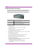
Introduction Overview of the Vertigo XG chassis The Vertigo XG unit is a 3RU rackmount rendering platform that incorporates redundant fans, three power supplies, and 1 TB RAID1-enabled storage (optional 2 TB RAID10 expansion). The only visible difference between the two models of the Vertigo XG is that the single channel model (XG21-e) has only one (1) discrete AES audio connector, while the dual channel model (XG22-e) has two (2) discrete AES audio connectors.
Introduction Front panel components The Vertigo XG’s front panel provides convenient access to the hard drives, two USB ports, a CD/DVD ROM drive, and a control panel containing six LEDs and three buttons for system monitoring and operation. Figure 1-1 identifies each component on the Vertigo XG’s front panel. SYSTEM ALERT / POWER FAILURE LAN 2 OVERHEAT / FAN FAIL HDD ACTIVITY LAN 1 POWER INDICATOR POWER CD/DVD ROM DRIVE HARD DRIVES FLOPPY DRIVE USB 2.0 CONNECTORS (2) Figure 1-1.
Introduction Rear panel components The Vertigo XG’s rear panel provides convenient access to the video card’s I/O connector, which provides 4 SD/HD SDI video outputs, a reference signal input, and AES audio input/output. The rear panel also provides access to the graphics card connector, as well as various I/O ports (RS-422, USB, Ethernet...etc.). Figure 1-2 identifies the components and connectors on the rear panel of the Vertigo XG chassis.
2 INSTALLATION AND QUICK START INSTRUCTIONS This chapter provides you with instructions for performing a first-time installation of the Vertigo XG device, as well as the initial setup tasks to get the device up and running. The procedure concludes by verifying the installation by previewing the playout of an asset in Vertigo XG’s Live Window and a broadcast monitor. CAUTION Vertigo XG devices should only be installed by trained personnel in a restricted access locations only.
Installation and quick start instructions Step # Task description 4 Start up the Vertigo XG device (page 2-14) • Plug the DVI monitor’s power cable into a power socket and power it on • Plug the Vertigo XG’s power supply cables into a power socket • Power on the Vertigo XG unit 5 Assign a new IP Address for the Vertigo XG device (page 2-16) 6 Verify the installation by previewing the playout of an asset (page 2-17) • Verify the Vertigo XG’s Output Resolution setting • Enable the Vertigo XG’s Live Wi
Installation and quick start instructions Unpacking and verifying the Vertigo XG shipped items The Vertigo XG device is packaged and shipped with the items listed in the table below. As you unpack the contents of the shipment, please verify the completeness and condition of the contents of your received shipment. We also recommend that before attempting to install the unit, you use the table below to familiarize yourself with each of the items related to the Vertigo XG.
Installation and quick start instructions Discrete (AES) audio breakout cable Single channel Vertigo XG units (XG21-e) have one discrete (AES) audio connector, while dual channel Vertigo XG units (XG22-e) have two discrete (AES) audio connectors. For each physical SDI video output, there will be a discrete audio breakout cable. Each discrete audio breakout cable contains 4 BNC inputs and 8 BNC outputs. Each BNC connector represents 1 stereo pair (2 channels) of digital AES/EBU audio.
Installation and quick start instructions System Recovery DVD package 2 x System Recovery DVDs These DVDs can be used to restore the Vertigo XG unit to its original factory default configuration. Note that one of the DVDs has a sticker with the Vertigo XG’s serial number, which identifies that particular Vertigo XG unit. Store these the System Recovery DVDs in a safe location. Do not misplace.
Installation and quick start instructions ATI FirePro kit The ATI FirePro kit items are not required during the installation of a factory configured Vertigo XG. The Vertigo XG uses the ATI FirePro graphics card.
Installation and quick start instructions Mounting the Vertigo XG chassis in a rack Included in the shipping package is a Rack mounting kit, which contains the rails, screws and washers required to mount the Vertigo XG chassis into an equipment rack. Note that the rails are designed to fit in racks with a depth of 28” to 33”. Due to the heavy weigh of the unit, the rack in which the Vertigo XG unit will be installed should be anchored to the building’s structure.
Installation and quick start instructions 2-8 3. Locate the five rail buttons on each side of the chassis and locate the five corresponding holes on each of the inner rails. (*Please note that one end of the hole is larger than the other end of the hole.) 4. Align the larger end of each hole against its corresponding button. Once all aligned, push the holes toward their corresponding buttons and the rail is placed on the chassis. 5.
Installation and quick start instructions 7. After you have installed the inner rails on the chassis, you are ready to install the outer rails of the rail assemblies to the rack. In the package, locate a pair of front (-short) and rear (-long) brackets. Please note that the brackets are marked with Up/Front arrows (-front) and Up/Rear arrows (-rear). 8. Secure the front (-short) bracket (marked with the Up/Front arrows) to the outer rail with two Type G screws. 9.
Installation and quick start instructions 13. Slide the Vertigo XG chassis into the rack as shown below. The chassis may not slide into the rack smoothly or easily when installed for the first time. Adjustments to the slide assemblies might be necessary to achieve a smooth insertion. CAUTION Due to the heavy weight of the Vertigo XG device, ensure that the rack is securely anchored onto a unmovable surface or structure before installing the chassis into the rack.
Installation and quick start instructions Cabling the Vertigo XG unit Once the Vertigo XG chassis is securely mounted in an equipment rack, you can connect the required cables to the rear connectors of the Vertigo XG unit. Figure 2-1 and the cabling procedure below provide step-by-step instructions for properly cabling the Vertigo XG unit.
Installation and quick start instructions To cable the Vertigo XG: 1. Connect the three (3) AC power cables to the power supply sockets on the rear panel of the Vertigo XG chassis. WARNING DO NOT plug the power cables into AC power sockets yet. 2. 3. Connect the Keyboard and Mouse to the USB connectors on the front or rear panel of the Vertigo XG. Two PS/2 connections are also available on the rear panel, should you prefer to use another type of keyboard and mouse.
Installation and quick start instructions SDI OUT C /KEY Both of these connectors are not used by the Vertigo XG. SDI OUT D /KEY 6. ANALOG REF IN Connect to a house reference (Analog Blackburst or HD Tri-Level). ANALOG REF LOOP OUT Optional connection. Use to feed a reference signal to another piece of equipment. Connect the Discrete (AES) audio breakout cable to the Vertigo XG’s Discrete audio connector(s).
Installation and quick start instructions Starting the Vertigo XG Once the Vertigo XG is properly racked and cabled, you can make the power connections and you can perform the first-time start up of the Vertigo XG unit. 1. Plug the monitor’s power cable into a power socket and power it on. 2. Plug the Vertigo XG’s power supply cables into a power socket. 3. Power on the Vertigo XG unit by pressing the POWER button on the unit’s front panel.
Installation and quick start instructions Xplay Xplay is the playout control application that the master control system or device uses to control the playout of video and graphics on the Vertigo XG device. Whether the Vertigo XG is a single or dual channel model, only one instance of Xplay is used to control the Vertigo XG device’s output.
Installation and quick start instructions Assigning a new IP address to the Vertigo XG device Factory configured Vertigo XG units are shipped with a dynamic IP address. Using DHCP is not recommend, so you must assign a new static IP Address to the Vertigo XG device. To change the Vertigo XG’s current dynamic IP address to a static IP address: 1. In the Vertigo Command Shell, type ipconfig and take note of the current IP configuration. 2.
Installation and quick start instructions Verifying the installation and setup by previewing the playout To verify that the Vertigo XG is properly connected and operating, we recommend that you use the local copy of Xplay to load and playout an asset in the Live window and broadcast monitor associated with the Vertigo XG’s Channel A. For dual channel Vertigo XG devices, we recommend performing the same verification tasks on Channel B.
Installation and quick start instructions Enable the Vertigo XG’s Live window For installation and troubleshooting purposes, the Vertigo XG is equipped with a preview window called the Live Window. The Live Window allows you to display a representation of the output channel’s playout directly on the Vertigo XG’s desktop. To enable the device channel’s Live Window: 1. If Channel A’s Dashboard is not already open, select the TOOLS>LAUNCH DASHBOARD menu command in the Vertigo XG’s Control Panel for Channel A.
Installation and quick start instructions Use Xplay to playout a graphic To verify that the Vertigo XG is properly connected and playing out, the following procedures has you add a template asset to the playlist, then cue and take the asset so that it plays out in the Live window, as well as the broadcast monitor. N OTE These instructions describe playing out on the Vertigo XG’s primary output (channel A).
Installation and quick start instructions Completing the quick start procedure With the Vertigo XG now capable of playing out graphics, we recommend that you disable the Live Windows as they put an unnecessary burden on the system’s resources during on-air playout. Since the mouse, keyboard and DVI monitor are only used during the setup and configuration procedures, you can also disconnect these peripherals from the Vertigo XG unit. To disable the Live Window: 1.
3 NEED FURTHER ASSISTANCE? Technical Support For technical assistance, please contact the Miranda Technical support centre nearest you: Americas Telephone: +1-800-224-7882 e-mail: support@miranda.com Asia Telephone: +81-3-5644-7663 e-mail: asiatech@miranda.com Europe, Middle East, Africa, UK Telephone: +44 (0) 1491 820222 e-mail: eurotech@miranda.com France (only) Telephone: +33 (0) 1 55 86 87 88 e-mail: francetech@miranda.
Need further assistance? Miranda’s Corporate headquarters You can also contact Miranda’s corporate headquarters at: Miranda Technologies Inc. 3499 Douglas-B.-Floreani St-Laurent, Quebec, Canada H4S 2C6 Tel. 514-333-1772 Fax. 514-333-9828 www.miranda.