Advanced Life Safety Solutions Advanced Life Safety Solutions FA-262 Fire Alarm Control Panel Canada 25 Interchange Way Vaughan, ON L4K 5W3 Tel: 905-660-4655 Fax: 905-660-4113 U.S.A. 60 Industrial Parkway Cheektowaga, NY 14227 Tel: 1-888-660-4655 Fax: 1-888-660-4113 Mircom 2002 Printed in Canada Subject to change without prior notice www.mircom.com Installation and Operator’s Manual LT-2015MIR Rev.
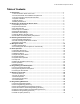
FA-262 Installation & Operator’s Manual Table of Contents 1.0 Introduction ...................................................................................................................... 1 1.1 The FA-262 Fire Alarm Control Unit .............................................................................. 1 1.2 Codes, Standards and Installation Requirements ......................................................... 1 1.3 Technical Support and General Information ......................................
FA-262 Installation & Operator’s Manual 9.0 Appendix: Table of Compatible Smoke Detectors ........................................................ 33 9.1 Smoke Detector Bases ................................................................................................. 35 9.2 Compatible 4-Wire Smoke Detectors ............................................................................ 35 9.3 Compatible Horns/Strobes ........................................................................................
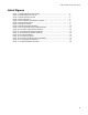
FA-262 Installation & Operator’s Manual List of Figures Figure 1: FA-262 cabinet with door closed .......................................................................... 4 Figure 2: FA-262 display and controls ................................................................................ 4 Figure 3: FA-262 Cabinet Overview .................................................................................... 4 Figure 4: Zone Label Insert ..................................................................
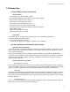
FA-262 Installation & Operator’s Manual 1.0 Introduction 1.1 The FA-262 Fire Alarm Control Unit General features •Two initiating device circuits, class B / style B •Two notification appliance circuits, class B / style Y (Power Limited) [can be wired as one NAC, class A / style Z] •One common alarm-actuated relay, form ‘C’ •One common trouble-actuated relay, form ‘C’ •AUX+ power output, 500 mA max.
FA-262 Installation & Operator’s Manual 1.3 Technical Support and General Information For technical support call 1-888-660-4655, or email techsupport@mircom.com. For general product information visit the Mircom web site: www.mircom.com. 1.
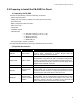
FA-262 Installation & Operator’s Manual 2.0 Preparing to Install the FA-262 Fire Panel 2.1 Unpacking the FA-262 The basic FA-262 package includes the following components: •Cabinet with hinged door •Display and control plate c/w display and control printed circuit board. •Zone label insert •Battery compartment dead front plate •Main control PCB •Transformer •Installation manual •Hardware pack -- 2 × NAC EOL resistors (4.7 K, 5%, ½ W) -- 2 × Zone EOL resistors (4.
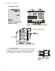
FA-262 Installation & Operator’s Manual 2.3 FA-262 Overview CPU FAULT Figure 1: FA-262 cabinet with door closed Figure 2: FA-262 display and controls Note: Use Security Screw(SPAENAUR #381-064) provided to meet UL 864 Rev 9 requirement Figure 3: FA-262 Cabinet Overview Zone Label Insert A zone label insert is installed in the zone window area. Reach behind the display/control panel and remove the blank insert.
FA-262 Installation & Operator’s Manual 2.4 Planning Your Installation Note: This system should be installed and serviced by qualified fire alarm installation professionals. As a minimum, the following points should be considered to ensure that the installation will be successful and proceed without delay. •Consult with your local AHJ to ensure that the overall system will meet all requirements. Have your plans reviewed and approved as required.
FA-262 Installation & Operator’s Manual 2.6 Module Current Ratings Standby Current (mA) DC Alarm Current (mA) DC Max. Alarm Current (mA) DC FA-262Control panel 90 425(*) 485 RTI-265 Remote trouble indicator 15 15 15 RAM-265 R.T.I. and remote 5 zone annunciator 15 20(*) 40 UDACT-286 DACT 45 60 60 RM-263 Relay module(**) 0 24 24 Module Note: *Current noted assumes ONE initiating zone is in alarm. The “Max. Alarm Current” assumes all zones are in alarm.
FA-262 Installation & Operator’s Manual 2.
FA-262 Installation & Operator’s Manual 3.0 Installing the FA-262 Fire Panel 3.1 Environmental Specifications Consider the following conditions when selecting a mounting location for the FA-262 panel: •Operating temperature: 32°F to 122°F / 0°C to 50°C •Humidity: 95% RH non-condensing •Close to a source of unswitched AC power 3.2 Panel Assembly and Modules Locations The panel comes completely assembled from the factory. Remove the lower dead front for access to the battery compartment.
FA-262 Installation & Operator’s Manual 3.
FA-262 Installation & Operator’s Manual 4.0 Wiring the FA-262 4.1 Wiring Specifications Figure 8: FA-262 Terminal Descriptions Terminal Label Description Notification Appliance Circuit # 1 NAC 1 (+, –) 24 VDC, Full-Wave Rectified voltage, 1.5 Amps max. Programmable as Steady or Temporal output on alarm. Supervised for opens, shorts and ground fault. Power limited. Notification Appliance Circuit # 2 NAC 2 (+, –) 24 VDC, Full-Wave Rectified voltage, 1.5 Amps max.
FA-262 Installation & Operator’s Manual Terminal Label Description Common Alarm relay, Normally Closed contact ALM NC The Common Alarm relay is normally de-energized. Contact is shown in the de-energized state. Contacts are rated 30 VDC, 2 Amps max. Z1+ Zone 1 positive input Zone 1 negative input Zone output is 24 VDC nominal to power 2-wire smoke detectors. Maximum current draw is 60 mA in alarm and is limited by the zone circuitry.
FA-262 Installation & Operator’s Manual Figure 10: Connecting 4-Wire Smoke Detectors 1. Program as zone type 01, instant alarm. 2. Maximum total loop wire resistance is 100 ohms. Zone Wiring Chart: Wire (Gauge) Distance (feet) Distance (meters) 18 7,690 2,345 16 12,195 3,717 14 19,230 5,861 Maximum loop resistance is 100 ohms. Maximum current in alarm is 60 mA. 4.
FA-262 Installation & Operator’s Manual NAC Wiring Chart Maximu m Total Loop (ohms) Maximu m Current (A) 18-Awg Wire 16-Awg Wire ft m ft m 14-Awg Wire ft m 12-Awg Wire ft m 8.00 0.25 615 188 978 297 1,538 469 2,500 762 5.00 0.50 308 94 488 149 769 235 1,250 381 2.70 0.75 205 63 325 99 513 156 833 254 2.00 1.00 154 47 244 74 385 117 625 191 1.60 1.25 123 38 195 59 308 94 500 152 1.30 1.
FA-262 Installation & Operator’s Manual Figure 15: Connecting the Alarm and Trouble Relays Figure 16: Connecting Optional Devices See installation sheets for the remote devices for detailed wiring and address setup. 1. Maximum of 4 MR-2605-T per panel. 2. Maximum of 4 MR-2605-AT per panel.
FA-262 Installation & Operator’s Manual To calculate the wire run distance for any gauge wire and any maximum current value, use the following formula: 1.25 Remix = Immix Amps ohms Remix × 1,000 Distance = 2(wire resistance in ohms per 1,000 feet) feet Secur-bus Capacitance Maximum wire capacitance for proper operation of the Secur-bus is 90 nF (nanofarad). Typical wire capacitance for 22 awg quad cable is 20 nF per 1,000 feet.
FA-262 Installation & Operator’s Manual 5.0 Panel Operation 5.1 Operating Sequences This section describes how the panel functions under various conditions. The choices you make in panel programming will also affect how the panel operates. Please see for information on how to program the panel, and descriptions of each of the programming options. 5.2 General Zone Fire Alarms Zone alarms have priority over all other annunciation.
FA-262 Installation & Operator’s Manual 5.4 Supervisory Zone Alarms When an alarm occurs on a supervisory zone (type 04), the corresponding zone supervisory LED begins flashing. The common supervisory LED and supervisory relay (supervisory relay is optional) turn on steady, and the buzzer turns on steady. If there was a trouble on that zone, the zone trouble LED turns off. The buzzer remains on until the trouble silence button is pressed.
FA-262 Installation & Operator’s Manual System Troubles 18 System faults Common Trouble LED Alarm zone open circuit – loss of EOLR Buzzer Trouble Relay turns on sounds ½ second on/ off deactivates Zone trouble LED turns on steady NAC open circuit or short circuit turns on sounds ½ second on/ off deactivates NAC1 or NAC2 trouble LED turns on Battery low voltage or disconnected turns on sounds ½ second on/ off deactivates Battery LED turns on Signals silenced automatically turns on sou
FA-262 Installation & Operator’s Manual 5.6 System Reset Operation To reset the system, press the ‘Reset System’ button. The panel will remove all power from the zones and the switched auxiliary relay for 10 seconds. During this 10 second period, the buzzer will beep twice every 2 seconds.
FA-262 Installation & Operator’s Manual 5.8 Walk Test (Installer function only) To do a walk test, all zone alarms, troubles and relays must be in their normal state. You can program the walk test to be either audible or silent (see “Audible Walk Test” on page 26). 1. To walk test the panel press the Walk Test button. The common trouble LED flashes and the buzzer sounds one short beep. The panel will be in walk test mode for one hour, or until you press the Walk Test button again. 2.
FA-262 Installation & Operator’s Manual 5.9 NAC operation See also “NAC Temporal/Steady Programming - Section 1 (‘NAC1’ LED on steady)” on page 25, and “NAC Auto-silence and Strobe Programming - Section 2 (‘NAC2’ LED on steady)” on page 25 for more information. Class ‘B’ operation selections: •Steady (default) – On alarm the NAC will turn on steady. It will turn off on either a manual or automatic signal silence.
FA-262 Installation & Operator’s Manual 6.0 Programming the FA-265 System 6.1 How to Program the FA-265 You can program the panel using the controls and indicator LEDs. There are no DIP switches to set for programming. Once programmed, the operating modes selected are maintained in non-volatile memory that will retain the programmed information even if all power is removed from the panel. Entering the Programming mode Note: All zone alarms must be reset prior to entering the programming mode.
FA-262 Installation & Operator’s Manual When you first enter programming mode, the panel will be at zone programming (section 0). Each programming section has one or more programming sub-sections (e.g. section 0 has sub-sections for zones 1 through 5). Use the Silence Trouble and Silence Alarm buttons to enter your programming choices: 1. Each sub-section in a section will have 2 or more programming settings, indicated by the panel Zone Supervisory and Zone Trouble LEDs.
FA-262 Installation & Operator’s Manual 6.2 Programming Section Descriptions Zone Programming (Section 0) In this zone programming section, the panel uses the zone alarm, supervisory, and trouble LEDs to indicate the programming as follows: CPU FAULT Zone type 00 – Null zone (Not used) The zone is not used. The zone is not supervised, alarms and troubles are ignored. The end-of-line resistor is not required.
FA-262 Installation & Operator’s Manual NAC Temporal/Steady Programming - Section 1 (‘NAC1’ LED on steady) You can individually program both NAC1 and NAC2 to sound in either a temporal or steady pattern. By default, both NAC outputs are programmed as steady. Temporal The NAC1 will sound the Temporal/ANSI Fire Pattern: 0.5 seconds ON, 0.5 seconds OFF, 0.5 seconds ON, 0.5 seconds OFF, 0.5 seconds ON, 1.5 seconds OFF, repeat. The NAC2 will sound the Temporal/ANSI Fire Pattern: 0.5 seconds ON, 0.
FA-262 Installation & Operator’s Manual Silence Inhibit and Walk Test Programming - Section 3 (‘Battery’ LED on steady) Signal Silence Inhibit Timer If the Signal Silence Inhibit Timer is enabled, when the first alarm is activated, the panel will begin a 60 second countdown. During this 60 seconds, users will not be able to turn off the NACs by pressing the Silence Alarm button. The timer is started on the first alarm only and is not restarted on subsequent alarms.
FA-262 Installation & Operator’s Manual 50/60 Hz Option - Section 5 (‘Signals Silence’ LED on steady) 50/60 Hz Option Reset Section Programming (All common trouble LEDs flashing) To Enter this Programming Section 1. Enter the installer programming mode, section 0 2. Press and hold the System Reset button for 2 seconds. The Z1 ALM LED and TRB LED will be ON and all the System Trouble LEDs will flash.
FA-262 Installation & Operator’s Manual Event Buffer Table 28 Display Event Steady Common Alarm LED Null Event Flashing Zone X Alarm LED Verified Zone X Alarm Steady Zone X Alarm LED Verified Zone X Alarm Restore Flashing Zone X Alarm LED and Flashing Zone X Supervisory LED Unverified Zone X Alarm Flashing Zone X Supervisory LED Zone X Supervisory Steady Zone X Supervisory LED Zone X Supervisory Restore Flashing Zone X Trouble LED Zone X Trouble Steady Zone X Trouble LED Zone X Trouble R
FA-262 Installation & Operator’s Manual 7.0 Startup of the FA-265 7.1 Prior to power up •Verify that all field wiring is free of shorts, opens and grounds and that end-of-line devices are connected and are the proper value. •Verify that all modules and internal cables are properly seated in their location. •Verify that all metal components are bonded to the incoming ground. Should measure zero ohms between any metal part and the incoming ground wire.
FA-262 Installation & Operator’s Manual 8.0 Programming Worksheets 8.1 Entering Programming Mode Please see “6.0 Programming the FA-265 System” on page 22 for complete instructions. Note: All zone alarms must be reset prior to entering the programming mode. While the panel is in the programming mode, the annunciators will show a trouble condition. To enter the Programming mode: 1. Press and hold the Walk Test button for two seconds (located behind the display PCB). 2.
FA-262 Installation & Operator’s Manual 8.2 Zone Programming (Section 0) Program each of the zones as one of the following types. (See “Zone Programming (Section 0)” on page 24.) Record your programming choices in the table below. ZONE ALARM LED On Zone No. 1 1 2 2 Type (00 05) Label 8.3 NAC Temporal/Steady Programming (Section 1) Please see “NAC Temporal/Steady Programming - Section 1 (‘NAC1’ LED on steady)” on page 25.
FA-262 Installation & Operator’s Manual 8.5 Silence Inhibit and Walk Test Programming (Section 3) Please see “Silence Inhibit and Walk Test Programming - Section 3 (‘Battery’ LED on steady)” on page 26. Settings ZONE ALARM LED On Programming Section 1 Signal Silence Inhibit Timer Enabled *Disabled 2 One Man Walk Test *Audible Silent * = Factory default 8.6 Waterflow Programming (Section 4) Please see “Waterflow Programming - Section 4 (‘Ground Fault’ LED on steady)” on page 26.
FA-262 Installation & Operator’s Manual 9.0 Appendix: Table of Compatible Smoke Detectors Panel CID Max.
FA-262 Installation & Operator’s Manual Panel CID Max.
FA-262 Installation & Operator’s Manual 9.1 Smoke Detector Bases Max.
FA-262 Installation & Operator’s Manual 9.
FA-262 Installation & Operator’s Manual Wheelock Type Cd Voltage (FWR) NS-2415W-FR(W) H/S 15 20-31 NS-241575W-FR(W) H/S 15/75 20-31 NS-2430W-FR(W) H/S 30 20-31 NS-2475W-FR(W) H/S 75 20-31 NS-24110W-FR(W) H/S 110 20-31 NS4-2415W-FR(W) H/S 15 20-31 NS4-241575W-FR(W) H/S 15/75 20-31 NS4-2430W-FR(W) H/S 30 20-31 NS4-2475W-FR(W) H/S 75 20-31 NS4-24110W-FR(W) H/S 110 20-31 NS = 2-wire, NS4 = 4-wire AS-2415W-FR(W) S 15 20-31 AS-241575W-FR(W) S 15/75 20-31 AS-243
FA-262 Installation & Operator’s Manual FCC Compliance Statement CAUTION: Changes or modifications not expressly approved by the manufacturer could void your authority to use this equipment. This equipment has been tested and found to comply with the limits for a Class B digital device, pursuant to Part 15 of the FCC Rules. These limits are designed to provide reasonable protection against harmful interference in a residential installation.
FA-262 Installation & Operator’s Manual Warranty & Warning Information Warning Please Read Carefully Note to End Users: This equipment is subject to terms and conditions of sale as follows: Note to Installers This warning contains vital information. As the only individual in contact with system users, it is your responsibility to bring each item in this warning to the attention of the users of this system.
FA-262 Installation & Operator’s Manual reasons, such as: the smoke detectors or heat detector may have been improperly installed or positioned; smoke or heat may not be able to reach the alarm initiating device, such as when the fire is in a chimney, walls or roofs, or on the other side of closed doors; and, smoke and heat detectors may not detect smoke or heat from fires on another level of the residence or building. •Software Most Mircom products contain software.
FA-262 Installation & Operator’s Manual Limited Warranty Mircom Technologies Ltd. warrants the original purchaser that for a period of two years from the date of manufacture, the product shall be free of defects in materials and workmanship under normal use. During the warranty period, Mircom Technologies Ltd. shall, at its option, repair or replace any defective product upon return of the product to its factory, at no charge for labor and materials.
FA-262 Installation & Operator’s Manual Out of Warranty Repairs Mircom Technologies Ltd. will at its option repair or replace out-of-warranty products which are returned to its factory according to the following conditions. Anyone returning goods to Mircom Technologies Ltd. must first obtain an authorization number. Mircom Technologies Ltd. will not accept any shipment whatsoever for which prior authorization has not been obtained. Products which Mircom Technologies Ltd.
Advanced Life Safety Solutions Canada 25 Interchange Way Vaughan, ON L4K 5W3 Tel: 905-660-4655 Fax: 905-660-4113 U.S.A. 60 Industrial Parkway PMB 278 Cheektowaga, NY 14227 Tel: 1-888-660-4655 Fax: 1-888-660-4113 © Mircom 2007 Printed in Canada Subject to change without prior notice www.mircom.