
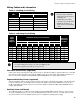
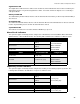
Specifications
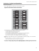
Indicators, Controls and Operations
22
Common Indicators
Buzzer
The Buzzer is activated by any of the following events:
If the Buzzer is turned on in response to a Non-Latching Trouble or Supervisory, it will be turned off if the condition
causing it goes away and there is no other reason for it to be on.
AC ON LED
The green AC ON Indicator will steadily illuminate as long as the main AC power is above minimum level. The
indicator turns OFF when the level falls below the power-fail threshold and the panel is switched to standby (battery)
power.
Common Alarm LED
The red Common Alarm Indicator steadily illuminates whenever the panel alarms on any initiating circuit. Since all
alarms are latched until the panel is reset, the Indicator will remain ON until then.
Common Supervisory LED
The amber Common Supervisory Indicator turns ON steady when there is a Supervisory Alarm in the Panel caused
by any Latching or Non-Latching Supervisory Circuit. The Indicator is turned OFF when all Non-Latching
Supervisory Circuits are restored and there are no active Latching Supervisory Circuits. Latching Supervisory
Alarms remain active until the Panel is reset.
Common Trouble LED
The amber Common Trouble Indicator turns ON steady when the panel detects any trouble condition. It turns OFF
when all Non-Latching Troubles are cleared.
Remote Trouble LED
The amber Remote Trouble Indicator flashes at the Trouble Flash Rate if there is trouble detected at a City Tie or
DACT, or if there is communication trouble detected with a Remote Annunciator or if a Remote Annunciator reports
a local trouble. It is turned off if these conditions go away.
Fire Drill LED
The amber Fire Drill Indicator illuminates steadily while Fire Drill is active.
Walk Test LED
The amber Walk Test Indicator illuminates steadily to indicate that the panel is in Walk Test Mode. If the Panel is left
in this mode for over an hour with no operator activity, the panel will return to normal and the Walk Test indicator will
turn OFF.
CPU Fail LED
The amber CPU Fail LED Indicator flashes at the Trouble Flash Rate to indicate a microprocessor failure on the
main board.
Auxiliary Disconnect LED
The amber Auxiliary Disconnect Indicator flashes at the Trouble Rate when the Auxiliary Disconnect button is
pressed. It turns OFF when the Auxiliary Disconnect button is pressed a second time. When ON flashing, the
Auxiliary Disconnect Indicator signifies that the Auxiliary Alarm Relay is disconnected. Depending on the
programming the auxiliary disconnect switch can also disconnect the common alarm and supervisory relay, see
Configuration section. When the Auxiliary Disconnect LED is flashing, the trouble buzzer will also sound.
Fire Alarm: Steady
Supervisory Alarm: Fast Flash
Trouble: Trouble Flash Rate