
Specifications

19
Installation
3.3 Chassis Board Connections
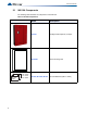
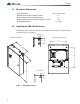
The Main Chassis is pre-installed in the INX-10A Enclosure as shown in Figure 1 INX-10A
Dimensions on page 16. The connections are shown in Figure 4 INX-10A Chassis Board
Connectors and Jumpers on page 19 and are described in Table 3 INX-10A Chassis Board
Connectors and Jumpers on page 19.
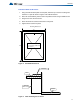
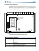
Figure 4 INX-10A Chassis Board Connectors and Jumpers
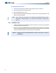
Table 3 INX-10A Chassis Board Connectors and Jumpers
Connector/Jumper Description
P1,2 Connection for 29VAC AC In
P3,4
Connection to Battery
Red(+) to P3
Black(-) to P4
JW1
Auxiliary Power Supervision. Factory set ON. Leave in place for
supervision. Remove for non-supervision.
JW2 Factory set (closed), leave in place
1
8
1
8
1
8
1
8
1
8
POWER ON
ADD. LINE
ACTIVITY/
ALARM
COMMON
TROUBLE
CPU FAIL
BATTERY/
CHARGER
TROUBLE
ACK.
BUTTON
JW1
P
P3 P4
P1 P2
AUX OUTPUT TROUBLE
SYNCH. OUT TROUBLE
GFAULT
JW2