SERVICE MANUAL FOR 8050QMA BY: ZX Xiao Repair Technology Research Department /EDVD Jun.
8050QMA N/B Maintenance Contents 1. Hardware Engineering Specification ……………………………………………………………………… 4 1.1 Introduction ……………………………………………………………………………………………………………….. 4 1.2 System Hardware Parts …………………………………………………………………………………………………... 7 1.3 Other Functions …………………………………………………………………………………………………………… 32 1.4 Power Management ………………………………………………………………………………………………………. 39 1.5 Appendix 1 : Intel ICH6-M GPIO Definitions …………………………………………………………………………. 42 1.
8050QMA N/B Maintenance Contents 5. Pin Description of Major Component …….………………………………………………………………. 78 5.1 Intel 915PM North Bridge ………………………………………………………………………………………………. 78 5.2 Intel ICH6-M South Bridge ……………………………………………………………………………………………… 88 t t n 7. Maintenance Diagnostics …………………………………………………………………………………… e e r c m e u S c c Do a 8. Trouble Shooting ……………………………………………………………………………………………. iT ial M t n e id f n o C 6. System Block Diagram ……………………………………………………………………………………… 98 99 7.
8050QMA N/B Maintenance Contents 8.12 PC Card Socket Failure ………………………………………………………………………………………………… 134 9. Spare Parts List ……………………………………………………………………………………………... 136 10. Reference Material …...…………………………………………………………………………………….
8050QMA N/B Maintenance 1. Hardware Engineering Specification 1.1 Introduction 1.1.1 General Description t t n e e r c m 1.1.2 System Overview e u S c c Do a iT ial M t n e id f n o C This document describes the brief introduction for MiTAC 8050QMA portable notebook computer system. The MiTAC 8050Q model is designed for Intel Dothan processor with 533MHz FSB with Micro-FCPGA package.
8050QMA N/B Maintenance (DMI) connecting with Intel ICH6-M. The Intel ICH6-M integrates three Universal Serial Bus 2.0 Host Controllers Interface (UHCI), the Audio Controller with AC97 interface, the Ethernet includes a 32-bit PCI controller, the IDE Master/Slave controllers, the SATA controller and Direct Media Interface technology.
8050QMA N/B Maintenance configurations, so that compact, high performance systems can be implemented easily. A full set of software drivers and utilities are available to allow advanced operating systems such as Windows ME, Windows 2000 and Windows XP to take full advantage of the hardware capabilities. Features such as bus mastering IDE, Plug and Play, Advanced Power Management (APM) with application restart, software-controlled power shutdown.
050QMA N/B Maintenance 1.
8050QMA N/B Maintenance 1.2.1 Intel Dothan Processors in Micro-FCBGA Package Intel Dothan Processors with 479 pins Micro-FCBGA package. It will be manufactured on Intel’s advanced 90 nanometer process technology with copper interconnect.
8050QMA N/B Maintenance • Supports tight ppm accuracy clocks for Serial-ATA and SRC. • Supports spread spectrum modulation, 0 to –0.5% down spread. • Uses external 14.318MHz crystal, external crystal load caps are required for frequency tuning. • Supports undriven differential CPU, SRC pair in PD# for power management. t t n e e 1.2.
8050QMA N/B Maintenance • Intel® Dothan processor • AGTL+ bus driver technology with integrated GTL termination resistors (gated AGTL+ receivers for reduced power) • Supports 32-bit AGTL+ host bus addressing • Supports system bus at 533MT/s (533 MHz) and 400MT/s (400 MHz) t t n e e r c m e u S c c Do a iT ial M t n e id f n o C • 2X Address, 4X data • Host bus dynamic bus inversion HDINV support • 12 deep, in-order queue Memory System • Directly supports to two DDR or DDR2 SDRAM channels, 64-bts wide
8050QMA N/B Maintenance • 256-MB, 512-MB and 1-GB technology using x8 and x16 devices.
8050QMA N/B Maintenance • Supports only 1.5-V AGP electrics • 32 deep AGP request queue • Hierarchical PCI-compliant configuration mechanism for downstream devices • Direct Media Interface (DMI) t t n e e r c m e u S c c Do a T al i 1.2.4 I/O Controller Hub :M Intel ICH6-M i t n e id f n • o C – Chip-to-chip interconnect between the GMCH and ICH6-M – DMI x2 and DMI x4 configuration supported – Bit swapping is supported – Lane reversal is not supported The ICH6 provides extensive I/O support.
8050QMA N/B Maintenance • Integrated Serial ATA host controller with independent DMA operation on two ports and AHCI support • Integrated IDE controller supports Ultra ATA100/66/33 • USB host interface with support for three USB ports; three UHCI host controllers; one EHCI high-speed USB2.0 Host controller • Integrated LAN controller t t n e e r c m e u S c c Do a iT ial M t n e id f n o C • System Management Bus (SMBus) Specification, Version 2.
8050QMA N/B Maintenance Pin out Compatible with CB1410 • PCI Interface – Compliant with PCI Local Bus Specification Revision 2.3 – Compliant with PCI Bus Power Management Interface Specification Revision 1.1 – Compliant with PCI Mobile Design Guide Version 1.1 t t n e e r c m e u S c c Do a iT ial M t n e id f n o C – Compliant with Advanced Configuration and Power Interface Specification Revision 1.0 • CardBus Interface – Compliant with PC Card Standard 8.
8050QMA N/B Maintenance • Memory Stick Interface – Compliant with Memory Stick PRO Format Specification Version 1.
8050QMA N/B Maintenance • Support parallel 4-wire power switch interface 1.2.6 AC’97 Audio System: Advance Logic, Inc, ALC655 The ALC655 is a 16-bit, full duplex AC'97 2.3 compatible six channels audio CODEC designed for PC multimedia systems, including host/soft audio and AMR/CNR based designs. The ALC655 incorporates proprietary converter technology to meet performance requirements on PC99/2001 systems.
8050QMA N/B Maintenance • Meets performance requirements for audio on PC99/2001 systems • Meets Microsoft WHQL/WLP 2.0 audio requirements • 16-bit Stereo full-duplex CODEC with 48KHz sampling rate • Compliant with AC’97 2.3 specifications t t n e e r c m e u S c c Do a iT ial M t n e id f n o C – 14.318MHz- 24.576MHz PLL to save crystal – 12.
8050QMA N/B Maintenance • Stereo MIC record for AEC/BF application • Supports Power Off CD function • Adjustable VREFOUT control Supports double sampling rate (96KHz) of DVD audio playback • Support 48KHz of S/PDIF output is compliant with AC’97 rev2.3 specification t t n e e r c m e 1.2.7 MDC: Pctel Modem Daughter Card PCT2303W u (Askey V1456VQL-P1) S c c Do a iT ial M t n e id f n o C • Power support: Digital: 3.3V; Analog: 3.
8050QMA N/B Maintenance small outline packages (AC’97 interface on PCT303A and phone-line interface on PCT303W). The chip set eliminates the need for an AFE, an isolation transformer, relays, opto-isolators, and 2-to 4-wire hybrid. The PCT2303W chip set dramatically reduces the number of discrete components and cost required to achieve compliance with international regulatory requirements. The PCT2303W complies with AC’97 Interface specification Rev. 2.1.
8050QMA N/B Maintenance • 2-4-wire hybrid • Integrated ring detector • High voltage isolation of 4000V • Support for “Caller ID” t t n e e r c m e u S c c Do a iT ial M t n e id f n o C • Compliant with FCC Part68, CTR21, Net4 and JATE • Low power standby • Low profile SOIC package 16 pins 10x3x1.55mm • Low power consumption • 10mA @ 3.3V operation • 1mA @ 3.
8050QMA N/B Maintenance Standard Features • Data – ITU-T V.90 (56Kbps), V.34 (4.8Kbps TO 33.6 Kbps), V.32 bis (4.8Kbps to 14.4Kbps), V.22 bis (1.2 bps to 2.4 Kbps), V.21 and Bell 103 and 212A(300 to 1200 bps) modulation protocol – Data Compression ITU-T V.42bis MNP Class 5 t t n e e r c m e u S c c Do a iT ial M t n e id f n o C – Error Correction ITU-T V.42 LAPM MNP 2-4 • Fax – ITU-T V. 17, V.29, V.27ter, V.
8050QMA N/B Maintenance 1.2.8 IEEE1394 VT6301S 1.2.8.1 Overview The VT6301S IEEE 1394 OHCI Host Controller provides high performance serial connectivity. It implements the Link and Phy layers for IEEE 1394-1995 High Performance Serial Bus specification release 1.0 and 1394a2000. It is compliant with 1394 Open HCI 1.0 and 1.1 with DMA engine support for high performance data transfer via a 32-bit bus master PCI host bus interface.
8050QMA N/B Maintenance • 3-deep physical post-write queue • 2-deep physical response queue • Dual buffer mode enhancements • Skip Processing enhancements t t n e e r • c m e u S c c o a 1.2.
8050QMA N/B Maintenance – Chip-Erase for PP Mode Single 3.0-3.6V Read and Write Operations Superior Reliability Firmware Hub Hardware Interface Mode Supports Intel High Definition Audio t t n e e r c m e u S c c Do a iT ial M t n e id f n o 1.2.
8050QMA N/B Maintenance • JEDEC standard 1.
8050QMA N/B Maintenance • Programmable burst lengths : 4 or 8 • Read burst interrupt supported by another READ • Write burst interrupt supported by another WRITE • Adjustable data – output drive strength t t n e e r • c m e u S • c c Do a • iT ial M t • n e id f 1.2.
8050QMA N/B Maintenance Management (OSPM) to achieve the most efficient power management possible. The RTL8100C(L) does not support CardBus mode as the RTL8139C does. In addition to the ACPI feature, the RTL8100C(L) also supports remote wake-up (including AMD Magic Packet, LinkChg, and Microsoft® wake-up frame) in both ACPI and APM environments. The RTL8100C(L) is capable of performing an internal reset through the application of auxiliary power.
8050QMA N/B Maintenance 2. Supports PCI clock 16.75MHz-40MHz 3. Supports PCI target fast back-to-back transaction 4. Provides PCI bus master data transfers and PCI memory space or I/O space mapped data transfers of RTL8100C(L)'s operational registers 5. Supports PCI VPD (Vital Product Data) 6. Supports ACPI, PCI power management t t n e e r c m e u S c c Do a iT ial M t n e id f n o C • Supports 25MHz crystal or 25MHz OSC as the internal clock source.
8050QMA N/B Maintenance • Advanced power saving mode when LAN function or wakeup function is not used • Uses 93C46 (64*16-bit EEPROM) to store resource configuration, ID parameter and VPD data • Supports LED pins for various network activity indications • Supports loop back capability t t n e e r • c m e u S c c o a D 1.2.12 Keyboard System: Winbond W83L950D iT ial M t n e id f n o C • Half/Full duplex capability Supports Full Duplex Flow Control (IEEE 802.
8050QMA N/B Maintenance • Support 2 PWM channels, 2 D-A and 8 A-D converters • Reduce Firmware burden by Hardware PS/2 decoding • Support 72 useful GPIOs totally • Support Flash utility for on board re-flash t t n e e r • c m e u S c c o a 1.2.13 Hard Disk Drive D iT ial M t n e id f n o C • • Support ACPI Hardware fast Gate A20 with software programmable IDE HDD The ICH6 IDE controller features one set of interface signals that can be enabled, tri-stated or driven low.
8050QMA N/B Maintenance • Ultra ATA/33/66/100: DMA protocol that redefines signals on the IDE cable to allow both host and target throttling of data and transfer rates of up to 33/66/100 MB/s t t n e e r c m e u S c c Do a iT ial M t n e id f n o C 31
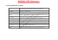
8050QMA N/B Maintenance 1.3 Other Functions 1.3.1 Hot Key Function Keys Combination Feature Meaning t t n e e r c m e u S c c Do a iT ial M t n e id f n o C Fn + F1 Power down Mini PCI power down Fn + F2 Reserve Fn + F3 Volume Down Fn + F4 Volume Up Fn + F5 LCD/external CRT switching Rotate display mode in LCD only, CRT only, and simultaneously display.
8050QMA N/B Maintenance 1.3.2 Power On/Off/Suspend/Resume Button 1.3.2.1 APM Mode At APM mode, Power button is on/off system power. 1.3.2.2 ACPI Mode t t n e e r c m e u S c c Do a iT ial M t n e 1.3.3 Cover Switch id f n o C At ACPI mode. Windows power management control panel set power button behavior. You could set “standby”, “power off” or “hibernate”(must enable hibernate function in power Management) to power button function.
8050QMA N/B Maintenance 3. Off 4. Hibernate (must enable hibernate function in power management) 1.3.4 LED Indicators t t n e e r c m e u S c c Do a iT ial M t n e id f n o C 1.3.4.1 Three LED Indicators at Front Side: From left to right that indicate BATTERY POWER, BATTERY STATUS and AC POWER -- AC POWER: This LED lights green when the notebook was powered by AC power line, Flashes (on 1 second, off 1 second) when entered suspend to RAM state with AC powered.
8050QMA N/B Maintenance connected, this indicator glows green if the battery pack is fully charged or orange (amber) if the battery is being charged. AC POWER: This LED lights green when AC is powering the notebook, and flash (on 1 second, off 1 second) when Suspend to RAM no matter using AC power or Battery power. The LED is off when the notebook is off or powered by battery. t t n e e r c m e u S 1.3.4.2 Seven LED Indicators: c c Do a iT ial M t n e id f 1.3.
8050QMA N/B Maintenance -- Battery Warning: Capacity below 10%, Battery Capacity LED flashes , and system beeps per 2 seconds. -- System will Suspend to HDD after 2 Minutes to protect users data. 1.3.5.2 Battery Low State After Battery Warning State, and battery capacity is below 5%, system will generate beep sound for twice per second. t t n e e 1.3.5.3 Battery Dead State r c m e u S c c Do a iT ial M t 1.3.6 Fan Power On/Off Management n e id f n o C When the battery voltage level reaches 11.
8050QMA N/B Maintenance When AC in or system main battery inside, CMOS battery will consume no power. AC or main battery not exists, CMOS battery life at less (220mAh/5.8uA) 4 years. 1.3.8 I/O Port t t n e e r c m e u S c c Do a iT ial M t n e id f n o C One Power Supply Jack One External DVI-I Connector For DVI Display Supports four USB port for all USB devices. One MODEM RJ-11 phone jack for PSTN line One RJ-45 for LAN. One IEEE1394 port One TV-Out port Reserve 1 connector on board for USB 2.
8050QMA N/B Maintenance Line in Jack 1.3.9 Battery Current Limit and Learning Implanted H/W current limit and battery learning circuit to enhance protection of battery.
8050QMA N/B Maintenance 1.4 Power Management The 8050MB system has built in several power saving modes to prolong the battery usage for mobile purpose. User can enable and configure different degrees of power management modes via ROM CMOS setup (booting by pressing F2 key). Following are the descriptions of the power management modes supported. t t n 1.4.1.1 Full on Mode e e r c m e u S c c Do a 1.4.1.2 Doze Mode iT ial M t n e id f n o 1.4.1.3 Standby Mode C 1.4.
8050QMA N/B Maintenance -- LCD: backlight off -- HDD: spin down 1.4.1.4 Suspend to DRAM The most chipset of the system is entering power down mode for more power saving.
8050QMA N/B Maintenance -- All system status will be restored when powered on again 1.4.2 Other Power Management Functions Implanted H/W current limit and battery learning circuit to enhance protection of battery. t t n e e r c m e u S c c Do a iT ial M t n e id f n o C 1.4.2.1 HDD & Video Access System has the ability to monitor video and hard disk activity. User can enable monitoring function for video and/or hard disk individually.
8050QMA N/B Maintenance 1.
8050QMA N/B Maintenance 1.
8050QMA N/B Maintenance 1.6 Appendix 2: W83L950D KBC Pins Definitions (1) Port Pin P0 P1 P3 0-7 0-7 0-7 0 1 2 3 4 5 6 7 0 1 2 3 4 5 6 7 0 1 2 3 4 5 6 7 P2 P4 P5 Function Scan matrix LPC enable GPIO x1 Implement KO[0..7] KO[8..15] KI[0..
8050QMA N/B Maintenance 1.
8050QMA N/B Maintenance 1.7 Appendix 3: 8050QMA Product Spec (1) Item CPU Core logic System BIOS Memory VGA Controller Description Intel® Pentium® M Processor (Dothan) 90nm, 2M L2, 533 MHz FSB Intel® Celeron® M processor, 90nm, 512K L2, 400 MHz FSB - CPU Thermal ceiling: 27W Intel 915PM + ICH6M - Dual Channel Memory Support - DDR2 400/533 Expandable to 2048MB(P) Inside 512KB Flash EPROM Include System BIOS, VGA BIOS t t n e e r c m e u S c c Do a iT ial M t n e id f n o C ACPI2.0; 2.
8050QMA N/B Maintenance 1.7 Appendix 3: 8050QMA Product Spec (2) Continue to previous page Item Description Audio/AV Function - AC97, support S/PDIF output - 5.1 channel analog output - 2.1 channel system speaker.
8050QMA N/B Maintenance 1.7 Appendix 3: 8050QMA Product Spec (3) Continue to previous page Item Description Communication PCI 10/100 LAN MDC 56K, V.90 Modem 802.11g wireless LAN (Mini PCI optional) with built-in Antenna Power Supply 6 cell Li-ion (2400mAH/3.7V) Battery pack Battery Life > 3HRs AC adapter Dimensions Weight Manuals Accessories SAFETY LOCK Architecture Sales Region Agency t t n e e r c m e u S c c Do a iT ial M t n e id f n o C Universal AC adapter 2 Pin 2.5*5.
8050QMA N/B Maintenance 2. System View and Disassembly 2.1 System View 2.1.1 Front View t t n e e r c m e u S c c Do a iT ial M t n e 2.1.
8050QMA N/B Maintenance 2.1.3 Right-side View CD/DVD-ROM Drive Kensington Lock 2.1.
8050QMA N/B Maintenance 2.1.5 Bottom View Hard Disk Drive CPU Battery Park Stereo Speaker Set t t n e e r c m e u S c c Do a 2.1.
8050QMA N/B Maintenance 2.2 Tools Introduction 1. Minus screw driver with bit size 2mm for notebook assembly & disassembly. 2mm t t n e e 2mm r c m e u S c c Do a iT ial M t n e id f n o C 2. Auto screw driver for notebook assembly & disassembly. Screw Size 1. M2.0 Tooling Auto-Screw driver Tor. 2.0-2.
8050QMA N/B Maintenance 2.3 System Disassembly The section discusses at length each major component for disassembly/reassembly and show corresponding illustrations.Use the chart below to determine the disassembly sequence for removing components from the notebook. NOTE: Before you start to install/replace these modules, disconnect all peripheral devices and make sure the notebook is not turned on or connected to AC power. t t n e e r c m e u S c c Do a iT ial M t n e id f n o C 2.3.1 Battery Pack 2.3.
8050QMA N/B Maintenance 2.3.1 Battery Pack Disassembly 1. Carefully put the notebook upside down. 2. Slide the two release lever outwards to the “unlock” position ( ), while take the battery pack out of the compartment ( ). (Figure 2-1) t t n e e r c m e u S c c Do a iT ial M t n e id f n o C Figure 2-1 Remove the battery pack Reassembly 1. Replace the battery pack into the compartment. The battery pack should be correctly connected when you hear a clicking sound. 2.
8050QMA N/B Maintenance 2.3.2 Keyboard Disassembly 1. Remove the battery pack. (Refer to section 2.3.1 Disassembly) 2. Open the top cover. 3. Loosen the five latches locking the keyboard.
8050QMA N/B Maintenance 4. Slightly lift up the keyboard and disconnect the cable from the system board, then separate the keyboard. (Figure 2-3) t t n e e r c m e u S c c Do a iT ial M t n e id f n o C Figure 2-3 Free the keyboard Reassembly 1. Reconnect the keyboard cable and fit the keyboard back into place. 2. Replace the keyboard fasten the five latches. 3. Replace the battery pack. (Refer to section 2.3.
8050QMA N/B Maintenance 2.3.3 CPU Disassembly 1. Remove the battery pack. (Refer to section 2.3.1 Disassembly) 2. Remove the seven screws fastening the CPU cover. (Figure 2-4) 3. Remove the four spring screws and two screws that secure the heatsink upon the CPU and disconnect the fan’s power cord from the system board.
8050QMA N/B Maintenance 4. To remove the existing CPU, loosen the screw by a flat screwdriver, upraise the CPU socket to unlock the CPU. (Figure 2-6) t t n e e r c m e u S c c Do a iT ial M t n e id f n o C Figure 2-6 Remove the CPU Reassembly 1. Carefully, align the arrowhead corner of the CPU with the beveled corner of the socket, then insert CPU pins into the holes. Tighten the screw by a flat screwdriver to locking the CPU. 2.
8050QMA N/B Maintenance 2.3.4 HDD Module Disassembly 1. Carefully put the notebook upside down. Remove the battery pack. (Refer to section 2.3.1 Disassembly) 2. Remove the two screws fastening the HDD compartment cover. (Figure 2-7) 3. Remove the one screw and slide the HDD module out of the compartment.
8050QMA N/B Maintenance 4. Remove the four screws to separate the hard disk drive from the bracket, remove the hard disk drive. (Figure 2-9) t t n e e r c m e u S c c Do a iT ial M t n e id f n o C Figure 2-9 Remove hard disk drive Reassembly 1. Attach the bracket to hard disk drive and secure with four screws. 2. Slide the HDD module into the compartment and secure with one screw. 3. Place the HDD compartment cover and secure with two screws. 4. Replace the battery pack. (Refer to section 2.3.
8050QMA N/B Maintenance 2.3.5 CD/DVD-ROM Drive Disassembly 1. Carefully put the notebook upside down. Remove the battery pack. (See section 2.3.1 Disassembly) 2. Remove the one screw fastening the CD/DVD-ROM drive. (Figure 2-10) 3. Insert a small rod, such as a straightened paper clip, into CD/DVD-ROM drive’s manual eject hole ( ) and push firmly to release the tray. Then gently pull out the CD/DVD-ROM drive by holding the tray that pops out ( ).
8050QMA N/B Maintenance 2.3.6 DDR-SDRAM Disassembly 1. Carefully put the notebook upside down. Remove the battery pack. (See section 2.3.1 Disassembly) 2. Remove the seven screws fastening the CPU cover. (Refer to the step 2 of section 2.3.3 Disassembly) t t n e e r c m e u S c c Do a iT ial M t n e id f n o C Figure 2-11 Remove the SO-DIMM 3. Pull the retaining clips outwards ( ) and remove the SO-DIMM ( ). (Figure 2-11) Reassembly 1.
8050QMA N/B Maintenance 2.3.7 Modem Card Disassembly 1. Carefully put the notebook upside down. Remove the battery pack. (Refer to section 2.3.1 Disassembly) 2. Remove seven screws fastening CPU cover. (Refer to step 2 of section 2.3.3 Disassembly) 3. Remove two screws fastening the modem card. (Figure 2-12) 4. Lift up the modem card and disconnect the cord. (Figure 2-13) t t n e e r c m e u S c c Do a iT ial M t n e id f n o C Figure 2-12 Remove two screws Reassembly Figure 2-13 Disconnect the cord 1.
8050QMA N/B Maintenance 2.3.8 LCD ASSY Disassembly 1. Remove the battery pack, keyboard, CPU, hard disk drive, CD/DVD-ROM drive, DDR and modem card. (See sections 2.3.1, 2.3.2, 2.3.3, 2.3.4, 2.3.5, 2.3.6 and 2.3.7 Disassembly) 2. Remove the eighteen screws fastening the housing and separate the antenna from the Mini PCI compartment. (Figure 2-14) 3. Disconnect the touch pad’s cable from the system board and remove the two screws, then free the top cover.
8050QMA N/B Maintenance 4. Remove the seven screws and lift the top shielding up, then free the top shielding. (Figure 2-16) 5. Separate the antenna and disconnect the two cables from the system board.
8050QMA N/B Maintenance 6. Remove the two screws and lift the two hinge covers up, then free the two hinge covers. (Figure 2-18) 7. Remove the four screws, then free the LCD assembly. (Figure 2-19) t t n e e r c m e u S c c Do a iT ial M t n e id f n o C Figure 2-18 Free the two hinge covers Reassembly Figure 2-19 Free the LCD assembly 1. Attach the LCD assembly to the base unit and secure with four screws. 2. Replace the antenna back into Mini PCI compartment. 3.
8050QMA N/B Maintenance 2.3.9 LCD Panel Disassembly 1. Remove the battery, keyboard, CPU, hard disk drive, CD/DVD-ROM drive, DDR, modem card and LCD assembly. (Refer to section 2.3.1, 2.3.2, 2.3.3, 2.3.4, 2.3.5, 2.3.6, 2.3.7 and 2.3.8 Disassembly) 2. Remove the two rubber pads and two screws on the corners of the panel. (Figure 2-20) 3. Insert a flat screwdriver to the lower part of the LCD cover and gently pry the frame out. Repeat the process until the cover is completely separated from the housing. 4.
8050QMA N/B Maintenance 5. Remove the four screws that secure the LCD brackets. (Figure 2-22) 6. Disconnect the cable to free the LCD panel. (Figure 2-23) t t n e e r c m e u S c c Do a iT ial M t n e id f n o C Figure 2-22 Remove the four screws Reassembly Figure 2-23 Free the LCD panel 1. Replace the cable to the LCD panel. 2. Attach the LCD panel’s brackets back to LCD panel and secure with four screws. 3. Replace the LCD panel into LCD housing and secure with ten screws. 4.
8050QMA N/B Maintenance 2.3.10 Inverter Board Disassembly 1. Remove the battery, keyboard, CPU, hard disk drive, CD/DVD-ROM drive, DDR, modem card, LCD assembly and LCD panel. (Refer to section 2.3.1, 2.3.2, 2.3.3, 2.3.4, 2.3.5, 2.3.6, 2.3.7, 2.3.8 and 2.3.9 Disassembly) 2. Remove the one screw fastening the inverter board, then free the inverter board. (Figure 2-24) t t n e e r c m e u S c c Do a iT ial M t n e id f n o C Figure 2-24 Free the inverter board Reassembly 1.
8050QMA N/B Maintenance 2.3.11 System Board Disassembly 1. Remove the battery, keyboard, CPU, hard disk drive, CD/DVD-ROM drive, DDR, modem card and LCD assembly. (Refer to sections 2.3.1, 2.3.2, 2.3.3, 2.3.4, 2.3.5, 2.3.6, 2.3.7 and 2.3.8 Disassembly) 2. Remove the two screws fastening the housing. (Figure 2-25) 3. Remove the two screws fastening the housing.
8050QMA N/B Maintenance 4. Disconnect the three speakers’ cables from the system board and separate the (R&L) rear covers. (Figure 2-27) 5. Remove the four screws and lift the system board from the housing.
8050QMA N/B Maintenance 6. Remove the two screws and separate the I/O bracket from the system board, then free the system board. (Figure 2-29) t t n e e r c m e u S c c Do a iT ial M t n e id f n o C Figure 2-29 Free the system board Reassembly 1. Fit the system board into the I/O bracket and secure with two screws. 2. Replace the system board into the housing and secure with four screws. 3. Reconnect the three speakers’ cables into the system board and replace the (R&L) rear covers. 4.
8050QMA N/B Maintenance 2.3.12 Touch Pad Disassembly 1. Remove the battery pack, keyboard, CPU, hard disk drive, CD/DVD-ROM drive, DDR and modem card. (See sections 2.3.1, 2.3.2, 2.3.3, 2.3.4, 2.3.5, 2.3.6 and 2.3.7 Disassembly) 2. Remove the top cover. (Refer to the steps 1-3 of 2.3.8 section Disassembly) 3. Remove the four screws and lift the shielding, then free the touch pad. (Figure 2-30) t t n e e r c m e u S c c Do a iT ial M t n e id f n o C Figure 2-30 Free the touch pad Reassembly 1.
8050QMA N/B Maintenance 3. Definition & Location of Connectors / Switches 3.
8050QMA N/B Maintenance 3. Definition & Location of Connectors / Switches 3.
8050QMA N/B Maintenance 4. Definition & Location of Major Components 4.1 Mother Board (Side A) PU2 : +3VS/+5VS Voltage Generator t t n e e r c m e u S c c Do a iT ial M t n e id f n o C PU3 : Charging Voltage Controller PU2 PU5 : CPU_Core Voltage Generator PU6 : +1.5VS/+1.05VS Voltage Generator PU12 : +1.8V_P/0.
8050QMA N/B Maintenance 4. Definition & Location of Major Components 4.
8050QMA N/B Maintenance 5. Pin Descriptions of Major Components 5.1 Intel 915PM North Bridge(1) Host Interface Signals Signal Name HADS# Type I/O AGTL+ HBNR# I/O AGTL+ HBPRI# O AGTL+ HBREQ0# I/O AGTL+ HCPURST# O AGTL+ HDBSY# I/O AGTL+ HDEFER# O AGTL+ HDINV[3:0]# I/O AGTL+ Host Interface Signals (Continued) Description Signal Name Host Address Strobe: The system bus owner asserts HADS# to indicate the first of two cycles of a request phase.
50QMA N/B Maintenance 5.1 Intel 915PM North Bridge(2) Host Interface Reference and Compensation Host Interface Signals (Continued) Signal Name HLOCK# HREQ[4:0]# Type I AGTL+ I/O AGTL+ 2X HTRDY# O AGTL+ HRS[2:0]# O AGTL+ HDPWR# O AGTL+ HCPUSLP# O CMOS Signal Name Description Host Lock: All CPU bus cycles sampled with the assertion of HLOCK# and HADS#, until the negation of HLOCK# must be atomic, i.e. PCI Express graphics access to System Memory is allowed when HLOCK# is asserted by the CPU.
8050QMA N/B Maintenance 5.1 Intel 915PM North Bridge(3) DDR / DDR2 SDRAM Channel A Interface Signal Name SA_DQ[63:0] SA_DM[7:0] SA_DQS[7:0] SA_DQS[7:0]# SA_MA[13:0] SA_BS[2:0] Type DDR / DDR2 SDRAM Channel A Interface (Continued) Signal Name Description I/O Data Bus: SSTL1.8/2 DDR / DDR2 Channel A data signal interface to the SDRAM data 2x bus. Single channel mode: Route to SO-DIMM 0 & SO-DIMM1 Dual channel mode: Route to SO-DIMM A I/O Data Mask: SSTL1.
8050QMA N/B Maintenance 5.1 Intel 915PM North Bridge(4) DDR / DDR2 SDRAM Channel B Interface Signal Name SB_DQ[63:0] SB_DM[7:0] SB_DQS[7:0] SB_DQS[7:0]# SB_MA[13:0] SB_BS[2:0] Type DDR / DDR2 SDRAM Channel B Interface (Continued) Description Signal Name I/O Data Lines: SSTL1.8/2 DDR / DDR2 Channel B data signal interface to the SDRAM data 2x bus. Single Channel mode: No connect. Dual channel mode: Route to SO-DIMM B NOTE: Signals do not exist in Intel 915GMS. O Data Mask: SSTL1.
8050QMA N/B Maintenance 5.1 Intel 915PM North Bridge(5) DDR / DDR2 Common Signals Signal Name SM_CK[1:0], SM_CK[4:3] SM_CK[1:0]#, SM_CK[4:3]# SM_CS[3:0]# SM_CKE[3:0] Type DDR / DDR2 Common Signals (Continued) Signal Name Description O SDRAM Differential Clock: SSTL1.8/2 The crossing of the positive edge of SM_CKx and the negative edge of its complement SM_CKx# are used to sample the command and control signals on the SDRAM.
8050QMA N/B Maintenance 5.1 Intel 915PM North Bridge(6) Analog TV-out Signals CRT DAC Signals Signal Name RED RED# GREEN GREEN# BLUE BLUE# REFSET HSYNC VSYNC Type O A Description Signal Name RED Analog Video Output: This signal is a CRT Analog video output from the internal color palette DAC. O RED# Analog Output: A This signal is an analog video output from the internal color palette DAC. This signal is used to provide noise immunity.
8050QMA N/B Maintenance 5.
8050QMA N/B Maintenance 5.1 Intel 915PM North Bridge(8) Serial DVO Interface. Serial DVO Interface (Continued) Signal Name Type Description Signal Name Type Description SDVOB_CLKP O PCIE O PCIE O PCIE O PCIE O PCIE O PCIE O PCIE O PCIE Serial Digital Video B Clock. Multiplexed with EXP_TXP_3. Serial Digital Video B Clock Complement. Multiplexed with EXP_TXN_3. Serial Digital Video B Red Data. Multiplexed with EXP_TXP_0. Serial Digital Video B Red Data Complement. Multiplexed with EXP_TXN_0.
8050QMA N/B Maintenance 5.1 Intel 915PM North Bridge(9) Reset and Miscellaneous Signals Signal Name RSTIN# PWROK H_BSEL [2:0] (CFG[2:0]) CFG[17:3] CFG[20:18] BM_BUSY# THRMTRIP# EXT_TS[1:0]# Type PLL Signals Description Signal Name I Reset In: HVCMOS When asserted this signal will asynchronously reset the GMCH logic. This signal is connected to the PLT_RST# output of the ICH6-M. This input has a Schmitt trigger to avoid spurious resets. This input buffer is 3.3-V tolerant.
8050QMA N/B Maintenance 5.1 Intel 915PM North Bridge(10) Power and Ground Interface Host DRAM Ball Name Power and Ground (Continued) Interface Description VTT (VCCP) FSB power supply (1.05 V) - (VCCP) VCCA_SM VCCSM VCCASM is the Analog power supply for SM data buffers used for DLL & other logic (1.5 V) System memory power supply (DDR=2.5 V; DDR2=1.8 V) VCC3G PCI Express / DMI Analog power supply (1.5 V) PCI Express Based Graphics /DMI VCCA_3GBG PCI Express / DMI band gap power supply (2.
8050QMA N/B Maintenance 5.2 Intel ICH6-M South Bridge(1) PCI Interface Signals Name Type AD[31:0] I/O C/BE[3:0]# I/O DEVSEL# I/O FRAME# I/O PCI Interface Signals (Continued) Description Name PCI Address/Data: AD[31:0] is a multiplexed address and data bus. During the first clock of a transaction, AD[31:0] contain a physical address (32 bits). During subsequent clocks, AD[31:0] contain data. The Intel® ICH6 will drive all 0s on AD[31:0] during the address phase of all PCI Special Cycles.
8050QMA N/B Maintenance 5.2 Intel ICH6-M South Bridge(2) PCI Interface Signals (Continued) Name PERR# REQ[0:3]# REQ[4]# / GPI[40] REQ[5]# / GPI[1] REQ[6]# / GPI[0] GNT[0:3]# GNT[4]# / GPO[48] GNT[5]# / GPO[17]# GNT[6]# / GPO[16]# PCICLK PCIRST# PLOCK# SERR# PME# Type I/O I O Serial ATA Interface Signals Description Name Parity Error: An external PCI device drives PERR# when it receives data that has a parity error. The ICH6 drives PERR# when it detects a parity error.
8050QMA N/B Maintenance 5.2 Intel ICH6-M South Bridge(3) LAN Connect Interface Signals Serial ATA Interface Signals (Continued) Name SATA[3]GP / GPI[31] SATALED# Type I OC O Description Name Serial ATA 3 General Purpose: Same function as SATA[0]GP, except for SATA Port 3. If interlock switches are not required, this pin can be configured as GPI[31]. Serial ATA LED: This is an open-collector output pin driven during SATA command activity.
8050QMA N/B Maintenance 5.2 Intel ICH6-M South Bridge(4) IDE Interface Signals (Continued) IDE Interface Signals Name Type DCS1# O DCS3# O DA[2:0] O DD[15:0] I/O DDREQ I DDACK# DIOR# / (DWSTB / RDMARDY#) O O Description IDE Device Chip Selects for 100 Range: For ATA command register block. This output signal is connected to the corresponding signal on the IDE connector. IDE Device Chip Select for 300 Range: For ATA control register block.
8050QMA N/B Maintenance 5.
8050QMA N/B Maintenance 5.2 Intel ICH6-M South Bridge(6) Power Management Interface Signals (Continued) Power Management Interface Signals Name Type PWRBTN# I RI# I SYS_RESET# I RSMRST# I LAN_RST# I WAKE# I MCH_SYNC# I SUS_STAT# / LPCPD# O SUSCLK O VRMPWRGD I Description Name Power Button: The Power Button will cause SMI# or SCI to indicate a system request to go to a sleep state. If the system is already in a sleep state, this signal will cause a wake event.
8050QMA N/B Maintenance 5.2 Intel ICH6-M South Bridge(7) Processor Interface Signals Name Type A20M# O CPUSLP# O FERR# IGNNE# I O INIT# O INIT3_3V# O INTR O Processor Interface Signals (Continued) Description Name Mask A20: A20M# will go active based on either setting the appropriate bit in the Port 92h register, or based on the A20GATE input being active. Processor Sleep: This signal puts the processor into a state that saves substantial power compared to Stop-Grant state.
8050QMA N/B Maintenance 5.2 Intel ICH6-M South Bridge(8) General Purpose I/O Signals 1,2 General Purpose I/O Signals 1,2 (Continued) Name Type Tolerance Power Well Description GPO[49] OD O V_CPU_IO `Core GPO[48] O 3.3 V Core N/A N/A N/A GPI[41] I 3.3 V Core GPI[40] I 5V Core GPIO[39:35] N/A N/A N/A GPIO[34:33] I/O 3.3 V Core GPIO[32] GPIO[47:42] Tolerance Power Well Description GPO[18] O 3.3 V Core This signal is fixed as input only and can be used instead as LDRQ1#.
8050QMA N/B Maintenance 5.2 Intel ICH6-M South Bridge(9) AC ’97/Intel ® High Definition Audio Link Signals Name Type ACZ_RST# O ACZ_SYNC O ACZ_BIT_CLK I/O ACZ_SDOUT ACZ_SDIN[2:0] O I Name AC ’97/Intel ® High Definition Audio Reset: Master hardware reset to external codec(s). AC ’97/Intel High Definition Audio Sync: 48 kHz fixed rate sample sync to the codec(s). Also used to encode the stream number. AC ’97 Bit Clock Input: 12.288 MHz serial data clock generated by the external codec(s).
8050QMA N/B Maintenance 5.2 Intel ICH6-M South Bridge(10) Functional Strap Definitions 1 Signal GNT[6]#/ GPO[16] LINKALERT # SPKR Usage When Sampled Top-Block Swap Rising Edge of Override PWROK Reserved GNT[5]#/ GPO[17] The signal has a weak internal pull-up. If the signal is sampled low, this indicates that the system is strapped to the “top-block swap” mode (ICH6 inverts A16 for all cycles targeting FWH BIOS space).
8050QMA N/B Maintenance 6.
8050QMA N/B Maintenance 7. Maintenance Diagnostics 7.1 Introduction Each time the computer is turned on, the system BIOS runs a series of internal checks on the hardware. This poweron self test (post) allows the computer to detect problems as early as the power-on stage. Error messages of post can alert you to the problems of your computer. t t n e e r c m e u S c c Do a iT ial M t n e id f n o C If an error is detected during these tests, you will see an error message displayed on the screen.
8050QMA N/B Maintenance 7.2 Maintenance Diagnostics 7.2.
8050QMA N/B Maintenance 7.3 Error Codes-1 Following is a list of error codes in sequent display on the MINI PCI debug board.
8050QMA N/B Maintenance 7.3 Error Codes-2 Following is a list of error codes in sequent display on the MINI PCI debug board.
8050QMA N/B Maintenance 8. Trouble Shooting 8.1 No Power(*1) 8.2 No Display(*2) t t n e e r c m e u S c c Do a iT ial M t n e id f n o C 8.3 VGA Controller Test Error LCD No Display 8.4 External Monitor No Display 8.5 Memory Test Error 8.6 Keyboard (K/B) Touch-Pad (T/P) Test Error 8.7 Hard Drive Test Error 8.8 CD-ROM Drive Test Error 8.9 USB Port Test Error 8.10 Audio Test Error 8.11 LAN Test Error 8.
8050QMA N/B Maintenance *1: No Power Definition Base on ACPI Spec. We define the no power as while we press the power button, the system can’t leave S5 status or none the PG signal send out from power supply. Judge condition: Check whether there are any voltage feedback control to turn off the power. Check whether no CPU power will cause system can’t leave S5 status.
8050QMA N/B Maintenance 8.1 No Power-1 When the power button is pressed, nothing happens, no fan activity is heard and power indicator is not light up. Check following parts and signals: No Power t t n e e r c m e u S c c Do a iT ial M t n e id f n o C Main Board Is the notebook connected to power (either AC adaptor or battery)? Yes No Board-level Troubleshooting Connect AC adaptor or battery. Try another known good battery or AC adapter.
8050QMA N/B Maintenance 8.1 No Power-2 When the power button is pressed, nothing happens, no fan activity is heard and power indicator is not light up.
8050QMA N/B Maintenance 8.1 No Power-3 When the power button is pressed, nothing happens, no fan activity is heard and power indicator is not light up. Main Voltage Map t t n e e r c m e u S c c Do a iT ial M t n e id f n o C PU507,PL514 P28 +1.05VS_P JS508~ JS510 P25 +VCCP L50 P6 +VCC_GMCH L34 P28 +DVMAIN PL514,PL515 PU6 L46 L519 L518 PU508,PL515 P28 +1.5VS_P JS511~ JS513 P25 +1.5VS L51 L43 L38 L63 L516 L36 P6 +1.5VS_DPLLA P6 +1.5VS_DPLLB P6 +1.5VS_HPLL P6 +1.
8050QMA N/B Maintenance 8.1 No Power-4 When the power button is pressed, nothing happens, no fan activity is heard and power indicator is not light up. A PL1 120Z/100M PF1 7A/24VDC 1 2~4 3 2 1 JO2,JO1 SPARKGAP_6 ADINP t t n e e r c m e u S c c Do a iT ial M t n e id f n o C PC501 1U PC502 0.01U PD501 PR502 RLZ24D 470K PC520 0.01µ G PC2 0.01U K +PWR_VDDIN PD502 SCS140P PR501 .01 8 7 6 5 S PR506 4.7K A PD505 SCS140P K PC528 0.
8050QMA N/B Maintenance 8.1 No Power-5 When the power button is pressed, nothing happens, no fan activity is heard and power indicator is not light up. Charge PQ503 AO4407 PL506 BEAD_120Z/100M PC533 10µ PR45 4.7K PR47 0 PR46 4.7K PC534 10µ G PC525 0.01µ 4 PC524 0.01µ PL507 3.0µH PD507 SSA34 t t n e e r c m e u S c c Do a iT ial M t n e id f n o C S ADINP P32 PL508 33µH 8 7 6 5 3 2 1 PD506 SSA34 PC536 0.01µ PC535 10µ PR135 2M PD509 BZV55C15V PC17 0.
8050QMA N/B Maintenance 8.1 No Power-6 When the power button is pressed, nothing happens, no fan activity is heard and power indicator is not light up. Discharge Q49 SI2301DS BATT D G L81 120Z/100M R378 100K t t n e e r c m e u S c c Do a iT ial M t n e id f n o C PC526 1000P +VDD3 8 7 6 5 RP502 10K 3 2 1 ADEN# PD505 SCS140P A K PR512 100K S D20 BAS32L +DVMAIN PQ506 AO4407 PC527 0.
8050QMA N/B Maintenance 8.1 No Power-7 When the power button is pressed, nothing happens, no fan activity is heard and power indicator is not light up. Power Controller +VDD3 U726 AHC1G08DCK +DVMAIN 5 18 +KBC_CPUCORE +VDD3_AVREF +VDD3 2 t t n e e r c m e u S c c Do a iT ial M t n e id f n o C H8_PWRON P27 PU2 LTC3728L H8_PWRON 1 H8_PWRON C326 22P P29 +DVMAIN +1.8V_P PU12 SC486 +0.
8050QMA N/B Maintenance 8.2 No Display-1 There is no display on both LCD and VGA monitor after power on although the LCD and monitor is known-good. No Display Monitor or LCD module OK? No Board-level Troubleshooting Yes Make sure that CPU module, DIMM memory are installed Properly. Display OK? Yes No 1.Try another known good CPU module, DIMM module and BIOS. 2.Remove all of I/O device ( HDD, CD-ROM…….) from motherboard except LCD or monitor.
8050QMA N/B Maintenance 8.2 No Display-2 ****** System Clock Check ****** L31 120Z/100M +3VS C80 2.2µ L32 120Z/100M C78 2.
8050QMA N/B Maintenance 8.2 No Display-3 ****** Power Good & Reset Circuit Check ****** +3VS From PU5 VRMPWRGD 12 PWROK RESET U20 MAX809 +3VS 3 VCC C374 0.
8050QMA N/B Maintenance 8.3 VGA Controller Test Error LCD No Display-1 There is no display or picture abnormal on LCD although power-on-self-test is passed. VGA Controller Failure LCD No Display 1. Confirm LCD panel or monitor is good and check the cable are connected properly. 2. Try another known good monitor or LCD module. Display OK? Yes Remove all the I/O device & cable from motherboard except LCD panel or extended monitor.
8050QMA N/B Maintenance 8.3 VGA Controller Test Error LCD No Display-2 There is no display or picture abnormal on LCD although power-on-self-test is passed.
8050QMA N/B Maintenance 8.4 External Monitor No Display-1 There is no display or picture abnormal on CRT monitor, but it is OK for LCD. External Monitor No Display 1. Confirm monitor is good and check the cable are connected properly. 2. Try another known good monitor. Display OK? Yes Connect the I/O device & cable to the M/B one at a time to find out which part is causing the problem. Yes Re-soldering.
8050QMA N/B Maintenance 8.4 External Monitor No Display-2 There is no display or picture abnormal on CRT monitor, but it is OK for LCD.
8050QMA N/B Maintenance 8.5 Memory Test Error-1 Extend DDRAM is failure or system hangs up. Memory Test Error t t n e e r c m e u S c c Do a iT ial M t n e id f n o C 1. Check if on board SDRAM chips are no cold solder. 2. Check the extend SDRAM module is installed properly. ( J713,J714) 3. Confirm the SDRAM socket (J713,J714) is ok,no band pins. Test OK? Yes No If your system host bus clock running at 266MHZ then make sure that SO-DIMM module meet require of PC 266.
8050QMA N/B Maintenance 8.5 Memory Test Error-2 Extend DDRAM is failure or system hangs up. +0.9VS R243,R263…. 56 J713 SA_BS#[0..2], SA_CAS#, SA_RAS#, SA_WE# S[A..B]_BS#[0..2], S[A..B]_CAS#, S[A..B]_RAS#, S[A..B]_WE# SA_MA[0..13], CKE#[0..1], CS#[0..1], ODT[0..1] S[A..B]_DQS#[0..7], S[A..B]_DQS[0..7] SA_DQS#[0..7], SA_DQS[0..7] S[A..B]_DM[0..7], S[A..B]_DQ[0..63] SA_DM[0..7], SA_DQ[0..63] NB_CLK_DDR[0,1,3,4], NB_CLK_DDR[0,1,3,4]# NB_CLK_DDR[0,1], NB_CLK_DDR[0,1]# SMBDATA P7 SMBCLK +1.
8050QMA N/B Maintenance 8.6 Keyboard (K/B) Touch-Pad (T/P) Test Error-1 Error message of keyboard or touch-pad failure is shown or any key does not work. Keyboard or Touch-Pad Test Error Is K/B or T/P cable connected to notebook properly? Yes Try another known good Keyboard or Touch-pad. Test Ok? No Yes No t t n e e r c m e u S c c Do a iT ial M t n e id f n o C Check J4, J5 for cold solder? Board-level Troubleshooting Yes Re-soldering. Correct it.
8050QMA N/B Maintenance 8.6 Keyboard (K/B) Touch-Pad (T/P) Test Error-2 Error message of keyboard or touch-pad failure is shown or any key does not work. t t n e e r c m e u S c c Do a iT ial M t n e id f n o C 71 +VDD3 +3VS P11 U709 +3VS 74 +KBC_CPUCORE R704 10K 55~62 KI[0..7] 39~54 KO[0..15] 69 SERIRQ Internal Keyboard Connector J4 R146 10K 17~24 P23 1~16 25 KBD_US/JP# P23 KBD_US/JP# South Bridge LFRAME# ICH6-M U13 LAD[0..
8050QMA N/B Maintenance 8.7 Hard Disk Drive Test Error-1 Either an error message is shown, or the drive motor spins non-stop, while reading data from or writing data to hard disk. Hard Disk Drive Test Error 1. Check if BIOS setup is OK?. 2. Try another working drive. Re-boot OK? Yes No Check the system driver for proper installation. Re - Test OK? No Yes t t n e e r c m e u S c c Do a iT ial M t n e id f n o C Board-level Troubleshooting Replace the faulty parts.
8050QMA N/B Maintenance 8.7 Hard Disk Drive Test Error-2 Either an error message is shown, or the drive motor spins non-stop, while reading data from or writing data to hard disk. J715 +5VS_HDD +5VS 3,4 L64 120Z/100MHZ t t n e e r c m e u S c c Do a iT ial M t n e id f n o C R439 470 C309 0.1µ C303 0.
8050QMA N/B Maintenance 8.8 CD-ROM Drive Test Error-1 An error message is shown when reading data from CD-ROM drive. CD-ROM Driver Test Error 1. Try another known good compact disk. 2. Check install for correctly. Test OK? Yes No Check the CD-ROM drive for proper installation. Re - Test OK? No Yes t t n e e r c m e u S c c Do a iT ial M t n e id f n o C Board-level Troubleshooting Replace the faulty parts.
8050QMA N/B Maintenance 8.8 CD-ROM Drive Test Error-2 An error message is shown when reading data from CD-ROM drive. R441 470 D27 CL-190G J710 R414 0 CD_LED# +5VS 37 +5VS_CDROM SD_D[0..15] +3VS P11 RSTDRV# Refer Section 8.2(No display-3) SDA1 U709 IDEIRQ SDDACK# SIORDY South Bridge SDIOW# SDDREQ SDIOR# ICH6-M SDA0 SDCS1S# SDCS3S# SDA2 38~42 L49 120Z/100MHZ R558 4.7K C208 0.1µ C209 0.1µ P14 C198 10µ SD_D[0..15] 6~21 RSTDRV# 5 +3VS R198 8.
8050QMA N/B Maintenance 8.9 USB Test Error-1 An error occurs when a USB I/O device is installed. USB Test Error Check if the USB device is installed properly. t t n e e r c m e u S c c Do a iT ial M t n e id f n o C Board-level Troubleshooting Test OK? Yes No Replace another known good USB device. Correct it. Replace Motherboard Re-test OK? No Yes Correct it.
8050QMA N/B Maintenance 8.9 USB Test Error-2 An error occurs when a USB I/O device is installed. U501 RT9701-CB +5V 3 R791 22 4 P SW_VDD3 23 From U13 USB_OC0# VIN CE VOUT0,1 P14 GND USBP0+ R180 0 USBP0- R192 0 R186 0 USBP1- USBP1+ U709 P USB_OC1# ICH6-M 3 2 4 1 4 1 3 2 R190 0 USBP2- R786 0 R787 0 3 4 2 L501 120Z/100M VIN CE VOUT0,1 P14 GND +VCC_USB_1 A2 A3 C502 0.1µ L1 120Z/100M 2 C4 0.1µ R10 33K R159 47K C2 150µ F504 1.
8050QMA N/B Maintenance 8.10 Audio Test Error-1 No sound from speaker after audio driver is installed. Audio Failure 1. Check if speaker cables are connected properly. 2. Make sure all the drivers are installed properly. Yes Test OK? No Try another known good speaker, CD-ROM. Re-test OK? No t t n e e r c m e u S c c Do a iT ial M t n e id f n o C Board-level Troubleshooting 1.If no sound cause of line out, check the following parts & signals: Correct it. Replace Motherboard Yes Correct it.
8050QMA N/B Maintenance 8.10 Audio Test Error-2 (Audio In) No sound from speaker after audio driver is installed. 1,9 +3VS C581 10µ U17 RT9167-47CB +5VS 1 2 3 VIN GND CE C351 10µ 4 ADJ AGND MIC1 C755 0.1µ C725 0.1µ C364 0.
8050QMA N/B Maintenance 8.10 Audio Test Error-3 (Audio Out) No sound from speaker after audio driver is installed. +5VS +AMPVDD L73 120Z/100M 19 7,18 VDD PVDD0/PVDD1 ROUT+ C734 0.1µ C735 0.1µ LOUT+ P22 AGND C356 1µ AMP_RIGHT 20 From previous page 23 C347 1µ +5VS +5VS R729 4.
8050QMA N/B Maintenance 8.11 LAN Test Error-1 An error occurs when a LAN device is installed. LAN Test Error 1.Check if the driver is installed properly. 2.Check if the notebook connect with the LAN properly. t t n e e r c m e u S c c Do a iT ial M t n e id f n o C Board-level Troubleshooting Test OK? Yes No Check if BIOS setup is ok. Correct it. Replace Motherboard Re-test OK? Yes Correct it.
8050QMA N/B Maintenance 8.11 LAN Test Error-2 An error occurs when a LAN device is installed. +3V R696 3.6K +3V 106 +AVDDL 111 +AVDDH +DVDD PCI_AD20 ICH_PME# P11 2 EECK CS P15 SK VCC R508 100 46 P15 31 44… PCLKRUN# 65 EEDI 3 C660 1µ 108 EEDO 4 DI 93C46 DO PCI_DEVSEL# 68 PCI_FRAME# 61 PCI_GNT3# 29 PCI_REQ3# South Bridge PCI_INTE# PCI_IRDY# PMDI0+ 12 2 PMDI0- 11 5 PMDI1+ 9 6 PMDI1- ICH6-M PCI_TRDY# PMDI2+ PMDI2- 18 PMDI3+ 19 PMDI3- R683 49.
8050QMA N/B Maintenance 8.12 PC Card Socket Test Error-1 An error occurs when a PC card device is installed. PC Card Socket Failure 1. Check if the PC Card device is installed properly. 2. Confirm PC Card driver is installed ok. Test OK? Yes No Try another known good PC Card or device.
8050QMA N/B Maintenance 8.12 PC Card Socket Test Error-2 An error occurs when a PC card device is installed. +3VS +3VS CARD_VCC +3VS 5,6 VCCA1/2 C628 0.1µ VCC5_EN# P11 PCI_PME# PCI_C/BE#[0..3] PCI_PAR, PCI_STOP# U709 PCI_SERR#, PCI_PERR# 1 VCC3_EN# 2 VPPD0 15 VPPD1 14 SHDN 5VA,B VCCD0 3.3VA,B P16 OC U509 VCCD1 VDDP0 VDDP1 C603 0.1µ AVCCC,B,A CP2211A AVPP 16 3,4 8 R604 10K +CARD_VCC +VPPOUT J8 11-13 10 C610 0.1µ P16 C650 0.1µ C657 0.1µ C662 0.
Reference Material Intel Pentium-M Processor Intel, INC Intel 915PM North Bridge Data Sheet Intel, INC Intel ICH6 South Bridge Data Sheet Intel, INC System Explode View Technology.Corp./MiTAC 8050QMA Hardware Engineering Specification Technology.Corp.
SERVICE MANUAL FOR 8050QMA Sponsoring Editor : Jesse Jan Author : ZX.Xiao Assistant Editor : Ping Xie Publisher : MiTAC International Corp. Address : 1, R&D Road 2, Hsinchu Science-Based Industrial, Hsinchu, Taiwan, R.O.C. Tel : 886-3-5779250 Fax : 886-3-5781245 First Edition : Jun. 2005 E-mail : Willy.Chen @ mic.com.tw Web : http: //www.mitac.com http: //www.mitacservice.