
Technical Specifications

USP2000-071
CCaappss && BBaasseess
1-800-
3
2
8-5
9
34 • www.USPconnectors.com
65
© Copyright 2007 USP Structural Connectors
®
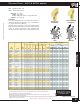
Column Caps – KCC & KECC series
KECC44
H
W
1
W
2
1
1
/
4
˝
1
1
/
2
˝
2
1
/
2
˝
2
1
/
2
˝
4˝
L
H
W
1
W
2
L
1
1
/
2
˝
2
1
/
2
˝
4˝
3˝
2˝
1
1
/
4
˝
KCC
KCC KECC
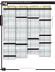
Ref. No. W1 W2 H KCC KECC KCC KECC 100% 100% 133% 160% 133% 160%
KCC325-4 CC3-1/4-4 7 3-1/4 3-5/8 6-1/2 11 7-1/2 (4) 5/8 (2) 5/8 (2) 5/8 21485 14650 2920 3505 1460 1750
KCC325-6 CC3-1/4-6 7 3-1/4 5-1/2 6-1/2 11 7-1/2 (4) 5/8 (2) 5/8 (2) 5/8 21485 14650 2920 3505 1460 1750
KCC44 CC44 7 3-5/8 3-5/8 4 7 5-1/2 (2) 5/8 (1) 5/8 (2) 5/8 15315 12030 3265 3920 1635 1960
KCC45 -- -- 7 3-5/8 5-3/8 6-1/2 11 7-1/2 (4) 5/8 (2) 5/8 (2) 5/8 24065 16405 3265 3920 1635 1960
KCC46 CC46 7 3-5/8 5-1/2 6-1/2 11 8-1/2 (4) 5/8 (2) 5/8 (2) 5/8 24065 18595 3265 3920 1635 1960
KCC47 -- -- 7 3-5/8 7-1/8 6-1/2 11 9-1/2 (4) 5/8 (2) 5/8 (2) 5/8 24065 20780 3265 3920 1635 1960
KCC48 CC48 7 3-5/8 7-1/2 6-1/2 11 9-1/2 (4) 5/8 (2) 5/8 (2) 5/8 24065 20780 3265 3920 1635 1960
KCC525-4 CC5-1/4-4 3 5-1/4 3-5/8 8 13 9-1/2 (4) 3/4 (2) 3/4 (2) 3/4 41640 30430 6795 8155 5040 5935
KCC525-6 CC5-1/4-6 3 5-1/4 5-1/2 8 13 9-1/2 (4) 3/4 (2) 3/4 (2) 3/4 41640 30430 6795 8155 5040 5935
KCC525-8 CC5-1/4-8 3 5-1/4 7-1/2 8 13 9-1/2 (4) 3/4 (2) 3/4 (2) 3/4 41640 30430 6795 8155 5040 5935
KCC54 -- -- 7 5-3/8 3-5/8 6-1/2 11 7-1/2 (4) 5/8 (2) 5/8 (2) 5/8 36095 24610 3455 4145 1725 2070
KCC55 -- -- 7 5-3/8 5-3/8 6-1/2 11 7-1/2 (4) 5/8 (2) 5/8 (2) 5/8 36095 24610 3455 4145 1725 2070
KCC55X -- -- 3 5-3/8 5-3/8 8 13 9-1/2 (4) 3/4 (2) 3/4 (2) 3/4 42655 31170 6795 8155 5040 5935
KCC57 CC6-7-1/8 7 5-3/8 7-1/8 6-1/2 11 9-1/2 (4) 5/8 (2) 5/8 (2) 5/8 36095 31170 3455 4145 1725 2070
KCC64 CC64 7 5-1/2 3-5/8 6-1/2 11 7-1/2 (4) 5/8 (2) 5/8 (2) 5/8 37815 25780 3455 4145 1725 2070
KCC66 CC66 7 5-1/2 5-1/2 6-1/2 11 7-1/2 (4) 5/8 (2) 5/8 (2) 5/8 37815 25780 3455 4145 1725 2070
KCC68 CC68 7 5-1/2 7-1/2 6-1/2 11 9-1/2 (4) 5/8 (2) 5/8 (2) 5/8 37815 32655 3455 4145 1725 2070
KCC74 CC74 3 6-7/8 3-5/8 8 13 10-1/2 (4) 3/4 (2) 3/4 (2) 3/4 54845 44295 6795 8155 5040 5935
KCC75X CC7-1/8-6 3 7-1/8 5-1/2 8 13 10-1/2 (4) 3/4 (2) 3/4 (2) 3/4 56875 45940 6795 8155 5040 5935
KCC76 CC76 3 6-7/8 5-1/2 8 13 10-1/2 (4) 3/4 (2) 3/4 (2) 3/4 54845 44295 6795 8155 5040 5935
KCC77 CC77 3 6-7/8 6-7/8 8 13 10-1/2 (4) 3/4 (2) 3/4 (2) 3/4 54845 44295 6795 8155 5040 5935
KCC77X CC7-1/8-7-1/8 3 7-1/8 7-1/8 8 13 10-1/2 (4) 3/4 (2) 3/4 (2) 3/4 56875 45940 6795 8155 5040 5935
KCC78 CC78 3 6-7/8 7-1/2 8 13 10-1/2 (4) 3/4 (2) 3/4 (2) 3/4 54845 44295 6795 8155 5040 5935
KCC84 CC84 3 7-1/2 3-5/8 8 13 10-1/2 (4) 3/4 (2) 3/4 (2) 3/4 60940 49220 6795 8155 5040 5935
KCC86 CC86 3 7-1/2 5-1/2 8 13 10-1/2 (4) 3/4 (2) 3/4 (2) 3/4 60940 49220 6795 8155 5040 5935
KCC88 CC88 3 7-1/2 7-1/2 8 13 10-1/2 (4) 3/4 (2) 3/4 (2) 3/4 60940 49220 6795 8155 5040 5935
KCC94 CC94 3 8-7/8 3-5/8 8 13 10-1/2 (4) 3/4 (2) 3/4 (2) 3/4 71095 57420 6795 8155 5040 5935
KCC96 CC96 3 8-7/8 5-1/2 8 13 10-1/2 (4) 3/4 (2) 3/4 (2) 3/4 71095 57420 6795 8155 5040 5935
KCC98 CC98 3 8-7/8 7-1/2 8 13 10-1/2 (4) 3/4 (2) 3/4 (2) 3/4 71095 57420 6795 8155 5040 5935
KCC104 -- -- 3 9-5/8 3-5/8 8 13 10-1/2 (4) 3/4 (2) 3/4 (2) 3/4 77190 62345 6795 8155 5040 5935
KCC106 CC106 3 9-5/8 5-1/2 8 13 10-1/2 (4) 3/4 (2) 3/4 (2) 3/4 77190 62345 6795 8155 5040 5935
1) Bearing loads are based on 625 psi perpendicular to grain loading; no further increase for duration of load is permitted.
2) Uplift loads have been increased 33-1/3% or 60% for wind or seismic loads; no further increase shall be permitted.
3) Allowable loads are based on lumber with a specific gravity of 0.50 and a moisture content of 19% or less.
4) All bolts shall meet or exceed the specifications of ASTM A 307.
5) Beams shall be designed to support the required loads. Beam shear may limit loads to less than listed loads for device.
6) The designer shall check post for required loads.
7) Spliced conditions must be detailed by the specifier to transfer tension loads between spliced members by means other than the column cap.
8) Uplift loads do no apply to splice conditions.
Bearing
1
Uplift
2,8
DF-L / SP
USP
Stock No.
Steel
Gauge
Column
or Post
KECC
KCC
Dimensions
Fastener Schedule
4
Allowable Loads (Lbs.)
3
L
Beam
KCC – Standard column cap.
KECC – End column version.
Materials: See chart
Finish: USP primer
C
odes:
N
ER 530, FL822, L.A. City RR 25337
Options: See page 66.
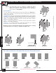
Installation:
•
Use all specified fasteners. See Product Notes, page 16.
• Bolt holes should be a minimum of
1
⁄
32
˝ to a maximum of
1
⁄
16
˝ larger than the bolt diameter.
• Beams shall be designed to support the required loads.
Beam shear may limit loads to less than listed loads for
device. A design professional shall determine the
adequacy of the post and beam to resist published loads.
Typical KCC
installation
Typical KECC44
installation
Bolts must be ordered
separately. See page 26
for available sizes.
continued on next page