
Technical Specifications

84
Angles & Straps
© 2015 MiTek. All rights reserved.
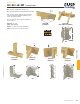
A3 / AC / JA / MP Framing Angles
Angles & Straps
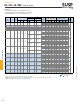
Ref. No. W1 W2 L Qty Type Qty Type 100% 115% 125% 160% 100% 115% 125% 160%
F1 450 515 560 590 390 445 485 495
F2 450 515 560 600 390 445 485 505
F3 210 240 260 335 135 155 170 215
MP3 LS30 18 2-1/4 2-1/4 3-3/8 3 10d 3 10d F1 340 395 430 485 295 340 370 470
MP5 LS50 18 2-1/4 2-1/4 4-5/8 4 10d 4 10d F1 455 525 570 730 390 450 490 625
MP7 LS70 18 2-1/4 2-1/4 5-7/8 5 10d 5 10d F1 570 655 715 910 490 565 615 785
MP9 LS90 18 2-1/4 2-1/4 6-7/8 6 10d 6 10d F1 685 785 855 1095 590 675 735 940
F1 340 390 425 540 290 335 365 465
F2 340 390 425 540 290 335 365 465
F3 155 180 195 250 100 115 125 160
F1 380 440 475 610 325 375 410 520
F2 380 440 475 610 325 375 410 525
F3 175 205 220 280 115 130 145 185
F1 450 520 565 725 390 445 485 620
F2 450 520 565 725 390 445 485 620
F3 210 240 260 335 135 155 170 215
F1 510 585 635 770 435 500 545 645
F2 510 585 635 815 435 500 545 700
F3 235 270 295 375 150 175 190 245
F1 565 650 705 905 485 560 605 775
F2 565 650 705 905 485 560 605 775
F3 260 300 325 415 170 195 210 270
F1 635 730 795 1015 545 625 680 870
F2 635 730 795 920 545 625 680 775
F3 295 340 370 470 190 220 240 305
F1 245 255 255 255 190 215 215 215
F2 -- -- -- -- -- -- 345 -- -- -- -- -- -- 290
F3 -- -- -- -- -- -- 165 -- -- -- -- -- -- 140
F1 510 570 590 590 380 440 480 495
F2 -- -- -- -- -- -- 535 -- -- -- -- -- -- 450
F3 -- -- -- -- -- -- 330 -- -- -- -- -- -- 275
F1 760 855 925 950 575 660 720 800
F2 -- -- -- -- -- -- 1015 -- -- -- -- -- -- 855
F3 -- -- -- -- -- -- 495 -- -- -- -- -- -- 415
F1 1015 1140 1230 1525 765 880 960 1225
F2 -- -- -- -- -- -- 1625 -- -- -- -- -- -- 1365
F3 -- -- -- -- -- -- 550 -- -- -- -- -- -- 460
F1 1270 1425 1540 1905 960 1100 1195 1535
F2 -- -- -- -- -- -- 1645 -- -- -- -- -- -- 1380
F3 -- -- -- -- -- -- 825 -- -- -- -- -- -- 695
1) Allowable loads have been increased 60% for wind and seismic loads; no further increase shall be permitted.
2) Minimum nail embedment shall be 1-1/2" for 10d nails; 1-5/8" for 16d nails.
3) Loads are shown per angle, and may be doubled if installed in pairs. When using a single angle, joist must be constrained from rotation.
4) For 1-1/2" lumber, use 0.98 of table load for 10d nails and 0.92 for 16d nails.
5)
NAILS:
10d x 1-1/2 nails are 0.148" dia. x 1-1/2" long, 10d nails are 0.148" dia. x 3" long, 16d nails are 0.162" dia. x 3-1/2" long.
New products or updated product information are designated in
blue font
.
10d x 1-1/2
10d x 1-1/2
Dimensions (in)
Header
Direction
of Load
2-1/2 2-1/2
62-1/2 2-1/2 5 16d
3
1-5/16 2-3/8
16d
10d x 1-1/2
16d 4
2-3/4 4
Fastener Schedule
2,4,5
10d x 1-1/2
Steel
Gauge
4
Code
Ref.
10d
1-1/2
USP
Stock No.
3
4-7/8
10d
16d
AC5 L50 16
AC9 L90 16 1-5/16
AC7 L70 16 1-5/16
16d
10d
Joist
A3
A23, GA1,
GA2, L30
18 1-7/16 1-7/16
10d
16d
10d x 1-1/2
10d
16d
72-1/2
JA5 -- -- 14
JA3 -- -- 14
8
10d x 1-1/2
JA1 A21 16 1-1/4 2
JA9 -- -- 14 9 10 102-1/2 2-1/2
16d 8
16d
2
4
1-1/2
6
JA7 -- -- 14
DF/SP
Allowable Loads (Lbs.)
1,3
S-P-F
Allowable Loads (Lbs.)
1,3
14,
F7,
R9
Corrosion
Finish
2-1/2
33
3
2-3/8 8-7/8
55
55
2-3/8 6-15/16
4
44
10d
16d
4
10d x 1-1/2
10d x 1-1/2
Corrosion Finish
Stainless Steel Gold Coat
HDG Triple Zinc
Corrosion Finish Stainless Steel Gold Coat HDG Triple Zinc
Corrosion
Finish
Stainless Steel
Gold Coat
HDG
Triple Zinc
Installation:
• Use all specied fasteners. See Product Notes, page 17.
• MP Framing Angles are fabricated at 100° and may be eld
adjusted by hand from 0° to 135°. Bend angle only once.