
Technical Specifications

121
Hangers
© 2015 MiTek. All rights reserved.
Top Mount Hanger Charts
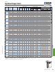
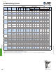
Floor
Uplift
1
Ref. No. W H D L TF
Top Face
Type Qty Type 100% 115% 125% 160%
KB612 B612 12 5-1/2 11-1/8 2-3/8 -- -- 2-1/2 4 6 NA20D 2 NA20D 4795 4920 4920 580 130
HDO612
HHB612,
HU612TF
12 5-1/2 11 2-1/2 -- -- 2-1/2 4 12 16d 6 16d 5060 5370 5500 1430
KHW612 HW612 3/10 5-1/2 11-1/8 2-1/2 10 2-1/2 4 -- -- NA20D 2 10d 5535 5535 5535 145
HDO614
B614, HHB614,
HU614TF
12 5-1/2 13 2-1/2 -- -- 2-1/2 4 14 16d 8 16d 5385 5410 5410 1710
KHW614 HW614 3/10 5-1/2 13-1/8 2-1/2 10 2-1/2 4 -- -- NA20D 2 10d 5535 5535 5535 145
HDO616
B616, HHB616,
HU616TF
12 5-1/2 15 2-1/2 -- -- 2-1/2 4 16 16d 8 16d 5715 6100 6240 1905
KHW616 HW616 3/10 5-1/2 15-1/8 2-1/2 10 2-1/2 4 -- -- NA20D 2 10d 5535 5535 5535 145
8 x 6 KHW86 HW86 3/10 7-1/2 5-3/8 2-1/2 10 2-1/2 4 -- -- NA20D 2 10d 5535 5535 5535 145
8 x 8 KHW88 HW88 3/10 7-1/2 7-1/8 2-1/2 10 2-1/2 4 -- -- NA20D 2 10d 5535 5535 5535 145
8 x 10 KHW810 HW810 3/10 7-1/2 9-1/8 2-1/2 10 2-1/2 4 -- -- NA20D 2 10d 5535 5535 5535 145
8 x 12 KHW812 HHB812, HW812 3/10 7-1/2 11-1/8 2-1/2 10 2-1/2 4 -- -- NA20D 2 10d 5535 5535 5535 145
8 x 14 KHW814 HHB814, HW814 3/10 7-1/2 13-1/8 2-1/2 10 2-1/2 4 -- -- NA20D 2 10d 5535 5535 5535 145
8 x 16 KHW816 HHB816, HW816 3/10 7-1/2 15-1/8 2-1/2 10 2-1/2 4 -- -- NA20D 2 10d 5535 5535 5535 145
2-1/2 glulam KHW26 -- -- 3/10 2-11/16 specify 4 10 2-1/2 4 -- -- NA20D 2 10d x 1-1/2 5295 5295 5295 145
3-1/8 glulam KHW3 HW3.25 3/10 3-1/4 specify 3 10 2-1/2 4 -- -- NA20D 2 10d 5535 5535 5535 145
5-1/8 glulam KHW5 HW5.25 3/10 5-1/4 specify 2-1/2 10 2-1/2 4 -- -- NA20D 2 10d 5535 5535 5535 145
1
)
U
p
lift Loads have been increased 60% for wind or seismic loads; no further increase shall be
p
ermitted.
2
)
KHW Glulam load values are based on 560
p
si
p
er
p
endicular to
g
rain loadin
g
.
3
)
Refer to the res
p
ective Nailer O
p
tions chart on
p
a
g
e 102 for han
g
ers installed on wood nailers.
4
)
Consult USP for additional Glulam sizes.
5
)
NAILS: 10d x 1-1/2" nails are 0.148" dia. x 1-1/2" lon
g,
10d nails are 0.148" dia. x 3" lon
g,
16d nails are 0.162" dia. x 3-1/2" lon
g,
NA20D nails are 0.192" dia. x 2-1/2" lon
g
and are included with KHW han
g
ers.
New
p
roducts or u
p
dated
p
roduct information are desi
g
nated in blue font.
Code
Ref.
Beam/
Joist Size
USP
Stock No.
Qty
Fastener Schedule
5
Header Joist
Steel
Gauge
Roof
Dimensions (in)
DF/SP
Allowable Loads (Lbs.)
2,3
2,
R12,
F1
2,
R12,
F1
Glulam Sizes
4
6 x 12
6 x 14
6 x 16
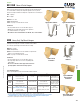
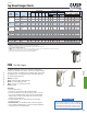
The FWH Fire Wall Hanger series is the best solution for attaching oor
framing to re rated walls in wood frame construction. The advanced design
allows the installation of the FWH before the drywall is attached and permits
the building project to be completely framed-up, and weather-tight before
the drywall sheathing work starts.
Materials: 14 gauge
Finish: USP Primer; FWH-T – G90 galvanizing
Options: See Specialty Options chart
Codes: See page 11 for Code Reference Chart
Patents: Pending
Installation:
• Use all specied fasteners.
• Install the face of hanger anges tight to stud wall framing.
• For proper installation, the end of the truss/joist should be 1-5/8” from
the face of the stud wall framing as shown in the Typical FWH drywall
installation gure resulting in a gap between the end of the truss/joist
and hanger no greater than 1/8".
• To achieve tabulated loads, the gap between the truss and hanger
should not exceed 1/8".
• Drywall Installation - Use the FWH-T template to slot cut the gypsum
board. See FWH-T Template Sequence on next page. Slide the drywall into
position and fasten to the framing members.
FWH
FWH Fire Wall Hangers
FWH side view
FWH hangers are tested per ASTM E814 standards. The test
report states “When installed on one side of a maximum 2
hour fire-rated wall assembly, the penetration of the USP FWH
Fire Wall Hanger through the gypsum board will not reduce
the fire resistive rating of the 2 hour fire resistive assembly.”
2 Hour Fire-Rating
Continued on next page
H
D
TF
W
Hangers
D
H
W
L
TF