
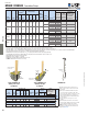
Technical Specifications

57
Holdowns
© 2015 MiTek. All rights reserved.
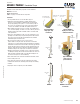
HPAHD / PAHD42 Foundation Straps
Designed to anchor wood framing to poured concrete foundations.
Materials: See chart
Finish: G90 galvanizing
Codes: See page 11 for Code Reference Key Chart
Installation:
• Use all specied fasteners. See Product Notes, page 17 .
• Bending the strap horizontally 90° to facilitate wall placement
may cause concrete behind the embedded strap to break away at
the top edge (spalling). If the spall is 1" or less from the top edge of
the concrete, no load reduction is necessary. If the spall is between
1" and 4", the allowable load is 0.90 of the published chart load.
• When installing on lumber less than 3-1⁄2" wide, wood splitting may
occur. To reduce splitting, use 10d x 1-1⁄2" nails or ll every other hole
with 16d common nails. Reduce allowable loads in accordance with
code requirements.
• Straps are to be installed at the edge of concrete. Install prior to pour
by nailing to form. Drive temporary nails through lowest two nail holes
into form. Concrete level should reach embedment line; minimum
embedment depths are listed in chart.
• Do not rely on these straps to secure concrete sections
together between cold joints; take other measures to transfer the
load. If there is a cold joint between slab and foundation, the minimum
embedment must be made into the foundation. Fastening opportunities
may be reduced because the slab pour level may be higher than some
nail holes. Using fewer fasteners will reduce allowable loads. Reduce
allowable load by the code capacity for each fastener not installed.
• Allowable loads based on a minimum concrete compressive strength
of 2,500 psi at 28 days, with one #4 horizontal rebar in the shear cone.
Rebar should be a minimum length of 2x embedment depth plus 12"
(see chart for exceptions in corner installations).
• Where fewer fasteners are used in the structural wood member, reduce
loads according to the code.
• There may be an increase in the amount of deection if the strap is
installed on the outside of the sheathing, versus directly to the framing
members.
• Strap may be bent one complete cycle to aid installation.
Typical HPAHD22
single pour edge
installation
Typical HPAHD22
single pour corner and
endwall installation
Typical HPAHD22
single pour rim
joist installation
HPAHD
PAHD42
HPAHD22 form board
installation
Continued on next page
H
W
W
D
Embedment
line
Embedment
line
Holdowns
2x embedment length
+ 12" min rebar length
12" min
rebar length
1/2" min
from corner
30" min
rebar length
1/2" min
from corner
Install (1) #4 rebar
in shear cone
Install (1) #4 rebar
in shear cone
(1) #4
rebar in
shear
cone
Nailed portion
13-1/2"
H
D
D
I
E
I
E
I
E