
Technical Specifications

100
Angles & Straps
© 2015 MiTek. All rights reserved.
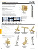
LTW12/MTW12
PWFS24
Permanent Wood Foundation Strap
Connects permanent wood foundation studs to rim joist to resist
lateral loads produced from ground pressure. The high load values
and positive placement nail gun installation make the PWFS24
practical for manufactured homes as well as site built homes.
Materials: 20 gauge
Finish: G90 galvanizing
Codes: See page 11 for Code Reference Chart
Installation:
• Use all specied fasteners. See Product Notes, page 17.
• Center strap on top plate over the stud.
• Attach center nail and bend inside end of strap downward.
• Install nails on inside of wall.
• Install oor system or place manufactured home on foundation.
• Form outside end of strap up the outside of rim and install nails.
Typical PWFS24
installation
PWFS24
Twist straps tie framing members to resist tension forces.
LFTA6 – 16 gauge.
LTW – 18 gauge, light-capacity.
MTW – 16 gauge, medium-capacity.
KTS – 16 gauge, medium-capacity with angled twist.
HTW – 14 gauge, heavy-capacity.
Materials: See chart
Finish: G90 galvanizing
Options: See chart for Corrosion Finish Options
Codes: See page 11 for Code Reference Chart
Installation:
• Use all specied fasteners. See Product Notes, page 17.
• Consult I-Joist manufacturer for web stiffener requirements,
and uplift limitations on joist and application.
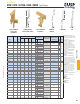
HTW / KTS / LFTA6 / LTW / MTW Twist Straps
1) Minimum nail embedment shall be
1-5/16" for 8d nails.
2) For installations where the strap
does not fall behind joist, the
designer shall be responsible to
determine suitability of rim to resist
the load.
3) NAILS: 8d nails are
0.131" dia. x 2-1/2" long.
Ref. No. W L Qty Type 100% 100%
PWFS24 PWF24 20 1-1/2 24 9 8d 775 645 130
1) Minimum nail embedment shall be 1-5/16" for 8d nails.
2) For installations where the strap does not fall behind joist, the designer shall be
be responsible to determine suitability of rim to resist the load.
3)
NAILS:
8d nails are 0.131" dia. x 2-1/2" long.
Code
Ref.
USP
Stock No.
Steel
Gauge
DF/SP
Allowable
Tension
Loads (Lbs.)
2
S-P-F
Allowable
Tension
Loads (Lbs.)
2
Dimensions
(in)
Fastener
Schedule
1,3
Typical LFTA6
truss-to-top
plate installation
Typical LFTA6
stud-to-rim joist
installation
Typical LFTA6 stud-to-top
plate installation
LFTA6
Typical LTW12 / MTW12
truss-to-top plate
installation
Typical LTW12 / MTW12
stud-to-rim joist
installation
Continued on next page
19-1/8"
6-1/2"
2-1/4"
8-3/8"
L1
L2
Uplift
Uplift
F1
F2
Equal number of
specied fasteners
at each end
Place strap so all
nail holes align
with rim joist
1-1/4"
1" Typ
Load
direction
24"
1-1/2"
Angles & Straps